20 7481 4897")


Technical Content: High
Read Time: 15 minutes
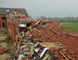
Geotechnical engineering involves the design and construction of structures interacting with soil and rock, such as retaining walls, foundations, tunnels and embankments, and Hawkins’ geotechnical engineers investigate failures of these structures.
With the rapid advancement of computer technology, full numerical modelling is now routinely carried out in geotechnical engineering and using this method to carry out ‘back-analysis’ of failures is an invaluable investigation tool, to understand the failure mechanism and the factors involved. However, producing a full numerical model is not straightforward; if the numerical analysis is not applied properly, the output can lead to both a defective design and its ensuing failure. However, if used with skill and care, full numerical modelling has enormous potential to explain the engineering behaviour of geotechnical structures and produce optimal and safe designs.
WHAT IS FULL NUMERICAL ANALYSIS?
In the context of geotechnical engineering, full numerical analysis is a numerical representation of the ground and structures within it or founded upon it. It is the ultimate analysis method that satisfies all theoretical geometric and static requirements, by discretising both the soil and the structure in the same way, as well as by applying a constitutive behaviour, which models the soil in a realistic manner.[i] Discretising is a process used to geometrically model the problem under investigation with visual regions defined by small nodetic manners and finite boundaries and is where the alternative name, Finite Element Analysis comes from. Constitutive behaviour means the stress-strain behaviour of the soil, i.e. how it deforms when a force is applied.
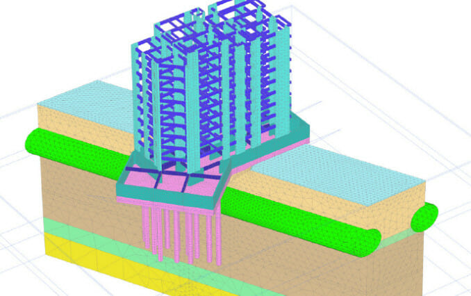
The example below shows the key steps needed to perform a full numerical analysis of a new earth embankment dam:
a. Definition of soil characteristics and layers (or stratigraphy) and choice of constitutive models:
First, a geotechnical engineer inputs the ground profile as interpreted from site investigation data. Then, an appropriate constitutive model is selected with the input of soil parameters to represent real soil behaviour.
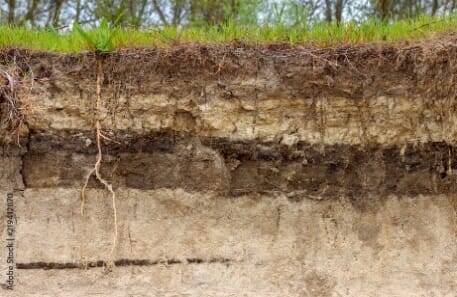
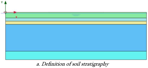
Soil stratigraphy in nature, vs defined soil stratigraphy in modelling
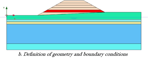
b. Definition of geometry and boundary conditions:
Next the engineer models structural elements within the soil mass with appropriate geometry and defines boundary conditions (displacements, forces, temperature, accelerations, etc.), which are applied to the mesh (or sections of it – see below) to represent conditions that might change at different stages in the analysis (called fixity).
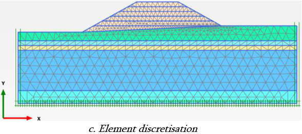
c. Element discretisation:
Then the finite element mesh is generated (normally done automatically by the software) The engineer checks the mesh quality, before manually adjusting or refining the mesh (if required) to increase the accuracy of the solution.
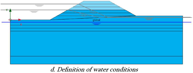
d. Definition of water conditions:
The engineer also sets boundary conditions for the groundwater flow, either for the construction stages or for the lifetime of the structure.
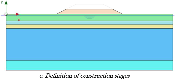
e. Definition of initial stress condition and construction stages:
Finally, the engineer defines the state of stress in the ground at the start of the analysis, (which is often a ‘greenfield’ condition, but must take into account previous overburden, which can lock-in high horizontal stresses), and creates sequential construction procedures to model different events or activities.
During the numerical simulation, structural members may be added and withdrawn to model field conditions. Retaining structures composed of several retaining walls, interconnected by structural components, can also be considered and, because the soil mass is modelled in the analysis, the complex interaction between raking struts (i.e. inclined props) or ground anchors and the soil can also be considered. The effect of time on the development of pore water (the water between soil and rock particles) pressures can also be simulated by including coupled consolidation (changes in soil volume, due to the rate at which this water can enter or leave its pores). No postulated failure mechanism or mode of soil behaviour is required, as these are predicted by the numerical analysis[iii]. The numerical analysis essentially simulates the complete history of the boundary value problem from the original, ‘greenfield’ condition, through both construction and long-term use of the structure.
As shown above, the full numerical model can be very complex, and the model design is usually unique for each application. Hence, the modeller must possess a great deal of skill, expertise and experience to successfully carry out a full numerical analysis, as well as to interpret its output.
WHY USE FULL NUMERICAL ANALYSIS?
For many years, geotechnical engineers have successfully used both conventional analytical and empirical methods (closed form solutions, limit equilibrium, beam-spring approaches etc) for design.
- Closed form solutions use simplified equations to model a problem, often based on experimental results
- Limit equilibrium methods analyse pre-defined failure mechanisms and shapes and so many of these must be reviewed to provide confidence that the worst case has been found
- Beam-spring approaches model the structure as beams and the soil as springs, with resulting limitations
Such methods still play a vital role in geotechnical engineering and should always be considered before carrying out a full numerical analysis. Nevertheless, under various conditions, their use might be considered inappropriate or, at best, limited[iv]. That is because conventional methods often use techniques based on assumptions that oversimplify the problem at hand. They lack the ability to account for all of the factors and variables the design engineer faces, and can severely limit the accuracy of the solution. A full numerical analysis can overcome many of these shortcomings, thereby offering many advantages over conventional approaches.
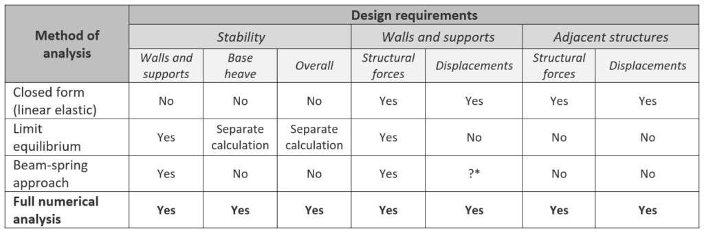
Taking the design of a retaining wall as an example, the table below, compares the capabilities of different methods of analysis. It is apparent that full numerical analysis can provide information on all design requirements. It can be used to examine situations that are not well understood, as well as go beyond the limits of normal design/construction practice. It can also be used to investigate the fundamentals of soil/structure interaction and to calibrate some of the conventional methods.
In addition to the capabilities discussed above, perhaps the most powerful use of full numerical analysis is to identify the sensitivity of predictions to variations in different parameters (ground conditions, the behaviour of structural elements, imposed constraints, methods of construction or construction sequences). Critical aspects of a design that require further development to obtain a robust solution can then be identified. As such, it is a design tool that can be used to assess risks in construction and to identify opportunities for value engineering.
Potentially, full numerical analysis can solve full three-dimensional problems and suffer none of the limitations of the conventional methods. At present, the speed of computer hardware restricts analysis of most practical problems to the two-dimensional plane strain or axisymmetric sections. However, with the rapid development in computer hardware, and its reduction in cost, the widespread adoption of full three-dimensional simulations is imminent[v].
In terms of the problems that can be addressed, full numerical analysis can be used for a range of soil-structure interaction problems and situations where deformations are important, such as a structure’s stability, or the effect that the construction of one structure has on another structure. The following is not an exhaustive list, but it illustrates the versatility of this approach in which linked thermal, hydraulic and mechanical behaviour can be considered:
- Cut-and-cover tunnels, bored tunnels and cast in-situ tunnels
- Onshore and offshore slopes and cuttings
- Embankments, including dams
- Onshore and offshore foundations
- Pipelines
- Earth retaining structures including embedded structures, anchored walls, gravity structures, reinforced earth structures[vi]
To obtain the most benefit from a full numerical analysis, it is important that:
- The software package used includes an appropriate stress-strain model for the relevant soil type and conditions, and can model structural interactions realistically;
- High quality site investigation results are available, including pre-excavation lateral stresses, as well as ground stiffness and strength;
- The user has the relevant training and experience of the software being used. Hawkins' geotechnical engineers have years of experience in using industry standard finite element software packages such as Plaxis.
In the second and third parts of this article, I will describe some case studies to show how it can be applied to forensic investigation of geotechnical and other soil/structure failures.
ABOUT THE AUTHOR
Shimin Zhuang is a Professional Engineer with a background in the design and construction of large-scale geotechnical solutions in Singapore and Hong Kong, including deep basements, retaining walls, reinforced soils, pipe jacking, deep shafts, deep foundations, pile-enhanced raft, segmental and cut & cover tunnels. He is experienced in both 2D & 3D geotechnical finite element analysis
[i] POTTS, D M and ZDRAVKOVIĆ, L (2012) “Computer analysis principles in geotechnical engineering”. In: J Burland, T Chapman, H Skinner and M Brown (eds) ICE manual of geotechnical engineering: Volume I, Chapter 6, Institution of Civil Engineers, London, UK (ISBN: 978-0-7277-5707-4)
[iii] POTTS, D M and ZDRAVKOVIĆ, L (1999a) Finite element analysis in geotechnical engineering, Volume 1, Theory, Thomas Telford, London, UK (ISBN: 978-0-72772-753-4)
[iv] O’BRIEN, A S and HIGGINS, K G (2020) The management of advanced numerical modelling in geotechnical engineering: good practice, C791, CIRIA, London, UK (ISBN: 978-0-86017-896-5)
[v] US ARMY CORPS OF ENGINEERS (1995) Geotechnical design by the finite element method, Technical Letter 1110-2-544, Department of the Army US Corps of Engineers, Washington DC, USA
[vi] Gaba, A, Hardy, S, Doughty, L, Powrie, W and Selemetas, D (2017) Guidance on embedded retaining wall design, C760, CIRIA, London, UK (ISBN: 978-0-86017-764-7)