20 7481 4897")


 Italiano
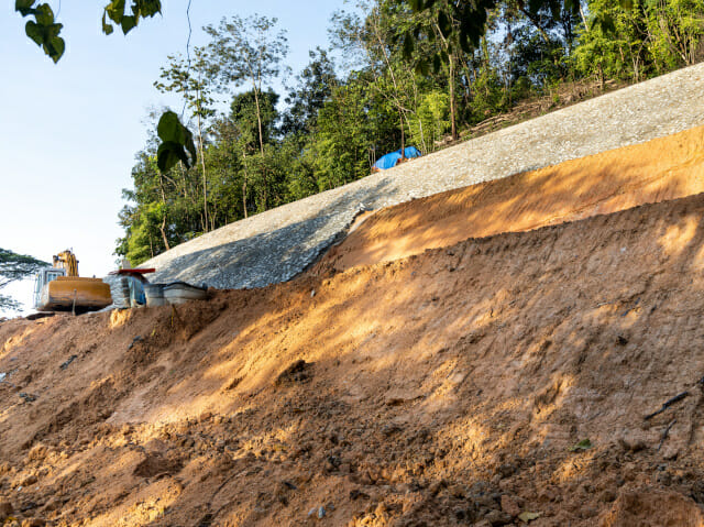
Technical Content: High
Read Time: 15 minutes
With the rapid advancement of computer technology, full numerical modelling is now routinely carried out in geotechnical engineering. However, producing a full numerical model is not straightforward; if the numerical analysis is not applied correctly, the output can lead to defective design and ensuing failure. If full numerical modelling is used with skill and care though, it has enormous potential to explain the engineering behaviour of geotechnical structures and produce both an optimal and safe design.
In the first part of this article, I introduced this technique and described both its advantages and disadvantages. In this second part of the article, I will describe two case studies to show how it can be applied to forensic investigation of geotechnical and other soil-structure failures. [A]
APPLICATION TO FORENSIC INVESTIGATION
For forensic investigations, the evidence obtained from both the desktop and site investigation must be reviewed and analysed to determine the cause of the failure. Failures seldom occur for a single reason, and especially for cases in which litigation is involved, the causes of failures are inevitably difficult to ascertain. Therefore, it is necessary to make various hypotheses regarding both why and how failures happen, as well as perform analyses to prove or disprove these hypotheses. Back‑analysis, which is often used in geotechnical engineering to estimate the material parameters on site, can be carried out using full numerical modelling to help establish failure scenarios, provide technical evidence, and assess the potential for future damage.
By using full numerical analysis, it is possible to quantify the sensitivity of predictions due to variations in different parameters and ground conditions. Based on the results of the analysis, the forensic engineer will then be able to offer opinions on either the relative responsibilities or the contributions to the ultimate failure [B].
In forensic investigations, the analytical tools adopted for full numerical analysis must be validated in accordance with a well-documented and stringent quality assurance program. For this reason, commercial software packages are preferred to in-house programs, because the former are usually well tested and improved based on the feedback from users [C].
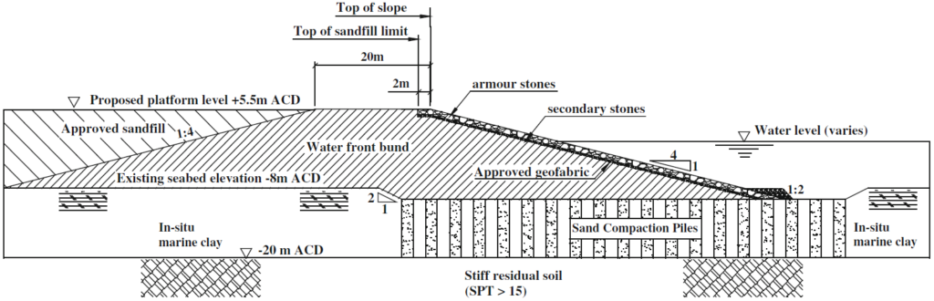
CASE STUDY 1: RECLAMATION BUND FAILURE IN SINGAPORE [D]
Reclamation bunds are constructed to form a stable perimeter, within which the dredged soil can be laid (usually by pumping) to form the reclaimed area.

During the construction of a perimeter bund for land reclamation in the western part of Singapore, the bund suddenly failed at one part of the reclaimed land site. A geotechnical expert was instructed by the loss adjuster to identify the cause of the bund failure.
Using independently evaluated soil parameters, the expert checked the consultant’s original bund design and verified that the design had achieved the desired safety factor of safety of 1.57. Design factors of safety are often published in technical standards, and range from 1.3, where soil properties are highly reliable to 3-4, where there is a low confidence in the reliability of the soil parameters. With such a high safety factor of 1.57, the bund slope should not have failed even if certain parameters and situations become less favourable.
Parametric studies were therefore conducted using full numerical analysis to evaluate the probable causes of failure. The expert identified that the important factors affecting the bund slope stability included the thickness and strength of the marine clay, overfilling behind the slope, the bund slope gradient, ground water variation, and the distance between the bund edge and the sand compaction pile edge. This table shows a summary of the safety factor values against slope stability under various scenarios.
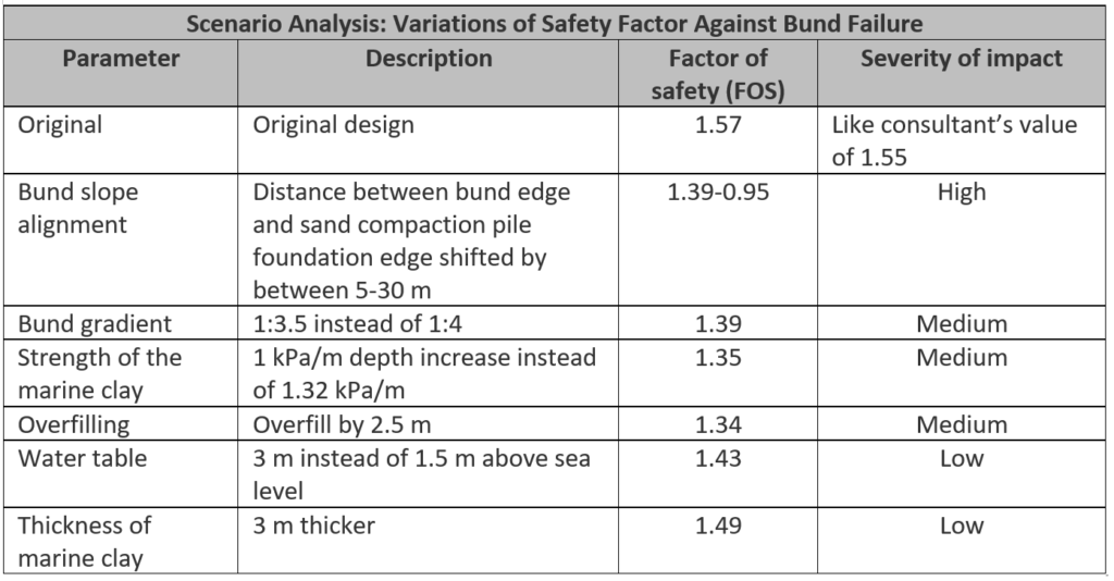
It can be seen above that a single factor alone probably could not trigger the bund failure, as the adopted safety factor was relatively high. Therefore, the cause of this bund failure must have been due to a combination of the scenarios.
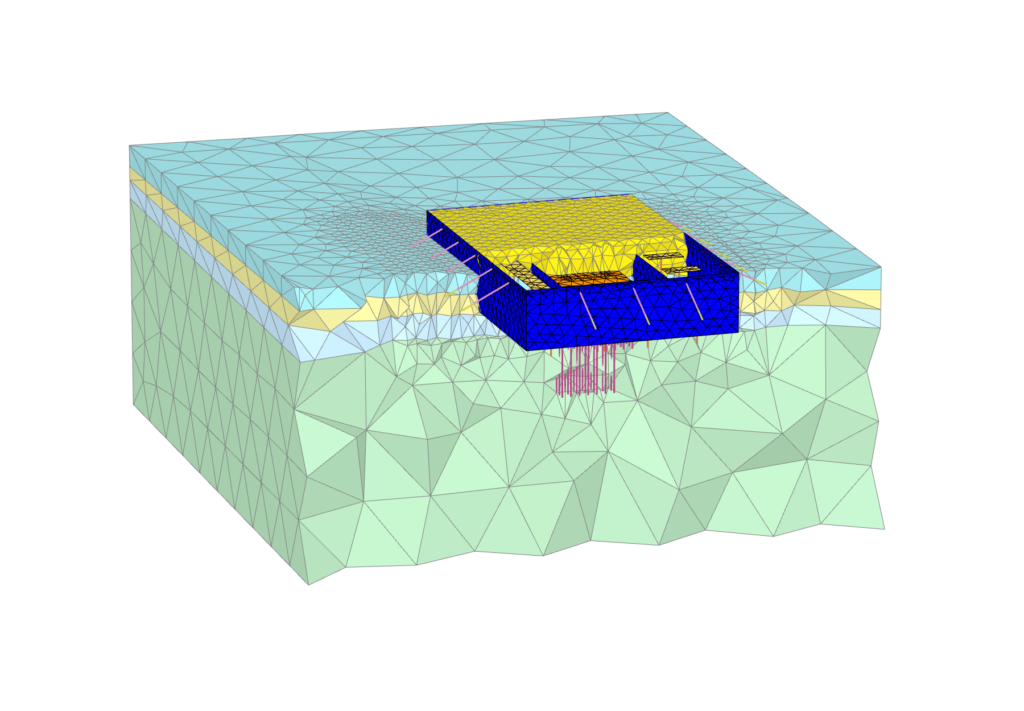
To examine the mechanism of the slip and the extent of soil yielding, the expert carried out a full numerical analysis under a variety of configurations. This image shows the different extents of soil yielding for thicknesses of marine clay varying from 10 to 15m.
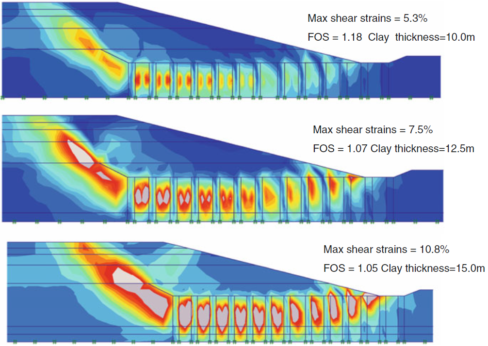
By evaluating the extent of the soil yielding, the analysis revealed that misalignment of the distance between the edges of the bund and the compaction pile foundation system would affect the bund stability the most. The predicted location of the greatest extent of the failure was indeed where the failure was observed.
CASE STUDY 2: LARGE LANDSLIDE IN QUEENSLAND, AUSTRALIA [F]
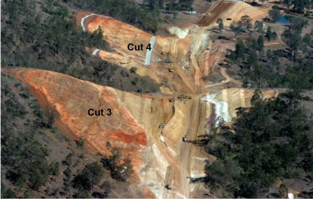
During bulk excavations to complete a road cutting, slumping and failure occurred along a section of the battered slope, known as Cut 3, following a period of significant rainfall.
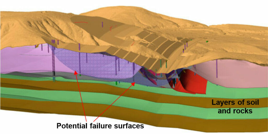
To characterise the landslip mass, both the geometry of the landslip and the rate of movement related to groundwater levels were investigated using a large number of drill holes installed with the following instruments:
- Inclinometers — devices used to measure horizontal movement within the ground
- Piezometers — devices used to measure groundwater levels or pore pressures in specific zones within the borehole
- Observation wells — wells used to monitor the pattern of water flow and long-term seepage in slopes
The inclinometer readings indicated the depth at which shear displacement was occurring at each of the drill hole locations. The initial results from the first inclinometers installed indicated that deep-seated movements were occurring in Cut 3.
Stability analysis for Cut 3 was carried out using two-dimensional full numerical modelling. The model below was set up to represent the conditions along cross sections oriented in the general direction of the maximum observed movement.
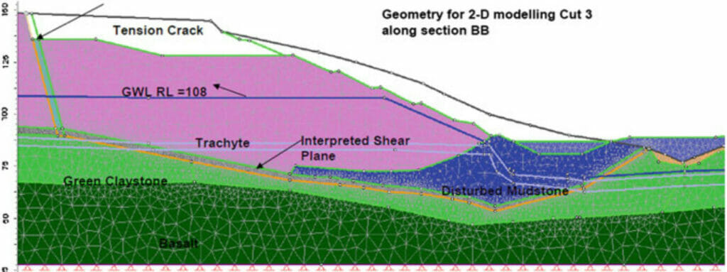
Inclinometer monitoring indicated that for Cut 3, the failure surface passed through a slickensided[1] zone beneath the trachyte[2] and near the surface of the claystone that underlies the cut. Stability modelling was constrained by explicitly modelling the measured geometry of the failure surface. Back-analyses were then carried out to assess the angle of internal friction of the material at the failure plane. The instrumentation data suggested that the rate of movement reduced to zero (i.e. Factor of Safety = 1.0) for an average groundwater level of RL[3] 85 m. Using this groundwater level, back-analysis indicated a friction angle of 8° for the material at the failure plane, which matched the laboratory test result undertaken on material recovered from the shear surface.
Forward-analyses, which aims to predict the ground behaviour with the calibrated model, were then carried out to assess factors of safety as a function of groundwater level, for the revised geometry following the remedial works. The results of these analyses helped the engineers to establish management protocols to allow measures such as road closures in the event of future groundwater level rises and predicted unacceptable reductions in factors of safety.
Hawkins regularly carries out causation investigation of geotechnical failures such as collapsed retaining walls and landslides, and where appropriate this can include full numerical back-analysis.
ABOUT THE AUTHOR
Er. Zhuang Shimin is a Professional Engineer with a background in the design and construction of large-scale geotechnical solutions in Singapore and Hong Kong, including deep basements, retaining walls, reinforced soils, pipe jacking, deep shafts, deep foundations, pile-enhanced raft, segmental and cut & cover tunnels. He is experienced in both 2D & 3D geotechnical finite element analysis.
[A] https://blog.virtuosity.com/how-to-speed-up-calcul…
[B] Robert, W. Day (2011) Forensic Geotechnical and Foundation Engineering 2nd Edition, Chapter 3 The Investigation, McGraw-Hill, USA (ISBN: 978-0-07-176133-8)
[C] Richard N. Hwang (2016) Developments in Geotechnical Engineering: Forensic Geotechnical Engineering, Chapter 9 Back Analyses in Forensic Geotechnical Engineering, Springer, India (ISBN: 978-81-322-2376-4)
[D] Leung CF, Tan SA, Shen RF (2005) Predictions versus performance of land reclamation bund. In: Proceedings of 16th international conference on soil mechanics and geotechnical engineering, vol 5. Osaka, pp 3540–3541
[E] Web article from https://raajje.mv/20615
[F] D.C. Starr, J. Woodford and D.F. Marks (2016) Developments in Geotechnical Engineering: Forensic Geotechnical Engineering, Chapter 16 Characterisation of Failure at a Large Landslide in SE Queensland by Geological Mapping, Laboratory Testing, Instrumentation and Monitoring, Springer, India (ISBN: 978-81-322-2376-4)
[1] In geology, a slickenside is a smoothly polished surface caused by frictional movement between rocks along the two sides of a fault.
[2] Trachyte is a type of light-coloured, very fine-grained extrusive igneous rock.
[3] These levels are referred to as “Reduced Levels” (RL) which means a height above (or below) a nominated datum.