20 7481 4897")


TYPES OF POWER GENERATION EQUIPMENT
The power generation market is complex and frequently changing. There is a wide variety of generating assets ranging from very traditional (steam turbines powered by burning coal), similar turbines powered by nuclear reactors, gas turbines that directly drive generators and may also provide their waste heat to boilers (to drive a steam turbine), reciprocating (piston) engines, hydro turbines, through to more recent (and immature) technologies such as wind turbines and solar (usually in the form of photovoltaics, known as ‘PV’ or ‘solar panels’).
Each type of generating asset has its own set of vulnerabilities that can lead to reduced efficiency, unexpected maintenance costs, loss of generation (and the consequent business interruption claims), damage to plant and in the worst case a serious incident that could cause extensive physical damage and even loss of life. Claims arising from large incidents can be dominated by Business Interruption losses, even though the physical damage might be extensive.
INVESTIGATING FAILURES
In such losses, the insurer might find itself stuck between the owner/operator and the Original Equipment Manufacturer (OEM) or installer, which might also be the maintenance provider. The owner/operator might be reluctant to volunteer information relating to the way in which the generating asset has been operated or maintained.
The OEM might carry out a Root Cause Analysis (RCA) that can generate a thick report with extensive technical details. This report might or might not demonstrate clearly where the responsibility for the loss lies. Such an RCA is dependent on technical interpretation both during the investigation and once the report has been generated. The report is also highly dependent on information from the Owner/Operator and the OEM.
The findings of an RCA can depend very strongly on fine technical details. Often these details are not simply measurable ‘Yes/No’ test results, but are judgements that rely on the skill and experience of those carrying out the analysis. Below I will discuss a hypothetical example of the fracture of compressor blading in a gas turbine.
GAS TURBINES – DESIGN AND OPERATIONAL CHALLENGES
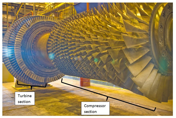
A gas turbine works on the “Suck Squeeze Bang Blow” principle familiar to those with a knowledge of traditional reciprocating piston engines. The turbine draws in air, which is then compressed and has fuel mixed with it, after which the mixture is ignited. The energy released in combustion is (partly) converted into mechanical movement and used to drive, for instance, electricity generators. Each of the phases of operation described above is carried out by separate stages of the machine, as summarised in the diagram below, but the main moving parts are usually connected to each other by way of one or more central rotating shafts (rotors). For simplicity we will consider an engine that contains just one rotating shaft that runs through the entire length of the turbine.
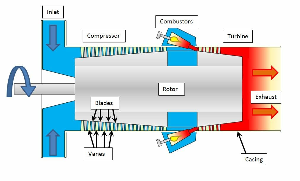
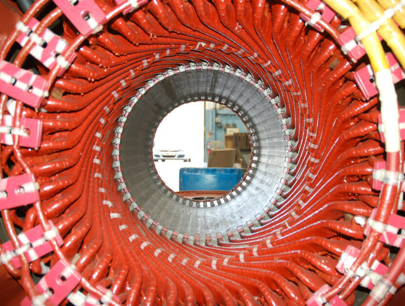
The incoming air is squeezed in the compressor stage. This consists of rows of aerofoil-shaped blades attached to the rotor (shown in the following photograph) and rows of similarly-shaped static vanes that are attached to the casing that surrounds the rotor. The air path is through an annular space between the rotor and the casing. The air is directed through this annulus by each row of vanes onto a row of blades and then on to the next row of vanes and so on, until the air has passed through the entire compressor stage. The blades and vanes of each row are shorter than their predecessors, such that the annulus becomes thinner and the air is compressed a little more at each row.
The compressed air passes into the combustor, where it is mixed with fuel before ignition occurs. The hot gas is then directed into a turbine stage that can be considered as being a compressor in reverse, in as much as that there is an annular gap with rows of blades and vanes that become progressively longer. Typically a gas turbine will contain many more rows of compressor blades (perhaps 20+) than turbine blades (perhaps 3 or 4). The turbine blades are driven by the energy in the hot gas from the combustor. Some of this energy is used to drive the compressor (by way of the common shaft) and some of the energy is used to turn a mechanical device such as a generator or a pump.
The design challenges encountered in the compressor are very different to those in the turbine. While the gas temperature at the later stages of the compressor can reach around 400°C, this is much lower than the temperatures faced by the first row of turbine blades – well over 1000°C.The components of the turbine must be designed and manufactured to withstand the effects of oxidation/corrosion and have sufficient strength at these high temperatures.
The efficiency of the compressor has a large bearing on the efficiency and power output of the machine as a whole. The drive for efficiency leads to increased stresses to which the aerofoils of the compressor blades and vanes are subjected. The aerofoils flex during operation, and under certain conditions, this flexure can result in resonant vibration, much like the response of a musical tuning fork. If the blades resonate for a prolonged period, fatigue cracking can occur. Hence, great efforts are made by gas turbine designers to avoid such resonance.
A TYPICAL GAS TURBINE FAILURE
Dr Wright has investigated a number of failures of gas turbine blades that resulted in very extensive damage. This is because the release of one blade triggers a cascade effect, where more blades are released through impact with the initial fragments, that go on to release yet more blades. Let us consider the fatigue failure of a compressor blade that leads to very extensive damage in the compressor section.
Fatigue cracking occurs when a component is stressed many times (at a load insufficient to cause instantaneous fracture), leading to initiation and gradual growth of a crack. Such cracks can be initiated by surface damage or sharp edges (for instance defects from manufacture) amongst other things that act as stress concentrators. Surface damage can be caused by small objects in the air stream passing through the turbine in normal operation. These are classed as foreign (when the objects come from outside the machine, e.g. a loose object left in the machine by accident or debris getting past the air filter) or domestic (when objects come from the machine itself, e.g. broken off pieces of compressor blade or pieces of loose casing).
The air passing through the machine can contain water droplets in the first few rows of the compressor, which can result in corrosion of the blades. Contamination in the liquid can make it more corrosive. Such contamination can come from the air being drawn into the compressor, particularly if the inlet air filters are in poor condition and the machine is in a coastal or industrial location. Corrosion can lead to pits on the surface of compressor blades that can initiate fatigue cracks.
Hence there are a number of possible causes of compressor blade failure, some of which (e.g. resonance) might have originated in the errors within either the machine design or operation, some of which (e.g. surface damage or corrosion from poor filtration) might have originated in errors within the machine maintenance or operation. Each of these potential causes might be the responsibility of a different party. In order to distinguish between these and identify the cause more accurately, the broken pieces (or what remains of them) are examined in detail. This is the part of the forensic investigation where experience and interpretation are of vital importance.
The first step is to identify the initiating damage. As is evident in Photograph 1, there is a large number of blades in the compressor section and a failure that leads to a blade release will tend to result in the cascade effect described above. In such cases, it is necessary to examine the remains of each blade from the first few damaged rows very carefully to identify the likely primary failure. Fatigue cracking leaves behind a characteristic signature on the component that can usually be found through visual examination.
I have conducted joint inspections with other parties such as OEM’s investigation teams in which detailed laboratory examinations are carried out. Once the component with the primary failure has been identified, the fracture is examined in detail to identify the “initiation point” of the fracture on the component. The nature of this initiation point (corrosion pit, impact damage, geometric feature etc.) is critical to establishing the root cause of the failure, as discussed above. Features on the surface known as “beachmarks” often help to identify the location of the initiation and the direction of crack growth as shown here:
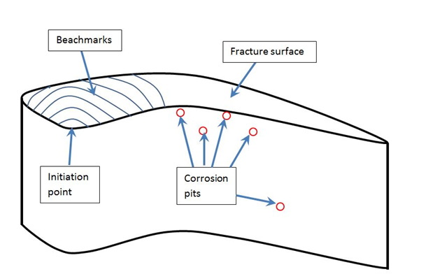
The presence of corrosion pitting in itself is not proof of cause. Minor pits distant from the initiation point might be irrelevant to the cause if there is a large impact from a foreign object at the initiation point. However, if the OEM is conducting the investigation and is concerned (for instance) that an error on its part during a planned maintenance strip-down led to some foreign object damage, or that there is a design defect in the blade, it might point to the existence of corrosion pitting that might have resulted from poor air filtration (under the control of the operator).
Such problems can be avoided by inspections jointly carried out by experts representing each of the interested parties, where the evidence can be evaluated thoroughly and the interpretations made by one party can be tested.
An independent investigation might provide additional benefits for the insurer and the operator in identifying risks that had not previously been considered, leading to better avoidance strategies for the future.
If you have an incident involving power generation equipment please give Dr Wright or one of his colleagues a call to discuss how we may be able to help.
ABOUT THE AUTHOR
Dr Nick Wright is a materials scientist with a background in Formula 1 engine development and power generation consultancy. He has investigated a large number of international claims relating to failures in industrial gas and steam turbines from all of the major manufacturers. Cases investigated include turbine blade and vane failures, compressor blade and vane failures, combustion hardware failures, efficiency/performance degradation, premature component degradation, shaft failures, gearbox and bearing failures. Dr Wright has worked on a wide range of turbine sizes from a few megawatts, through aero-derivatives to the largest industrial units with output in excess of 250MW. He has also investigated failures involving large reciprocating diesel engines and pumps and is available to attend site worldwide at short notice.