20 7481 4897")


 Italiano
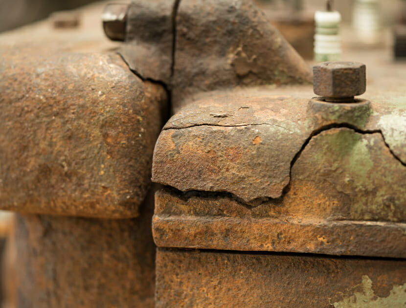

Brasses have been used for many thousands of years and can be used for decorative structures such as the Benin ‘Bronzes’ (actually made of brass) or, more recently, for architectural uses and for plumbing applications, to name a few (Photograph 1).

The term ‘brass’ can be used to described a wide range of copper (Cu) – zinc (Zn) alloys, with small additions of other alloying elements, e.g. lead, arsenic, tin, etc. Generally, brasses can be manufactured cheaply, in large volumes, and provide a range of useful mechanical properties: hardness, strength, ductility, wear resistance, ease of machinability, corrosion resistance, etc. The properties of brass can be altered by the addition or removal of chemical elements, or by heat treatment.
It follows that the performance of brass components often relies on correct property specification and manufacture. If, for instance, a brass application requires exemplary corrosion resistance, but the brass component has been incorrectly manufactured or specified, it will be unlikely to perform effectively and may fail prematurely.
This article will concentrate on the use of brass in plumbing applications, such as water or oil supply systems. In these applications, brasses are often used to form compression joints
(e.g. Photograph 2). In order to make a joint like this, a pipe is inserted through the back nut, through a metal olive and to the shoulder stop of the fitting body. The back nut is then screwed onto the fitting body and tightened using a spanner to the number of turns specified by the manufacturer (if that information is provided).
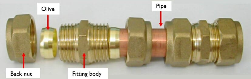
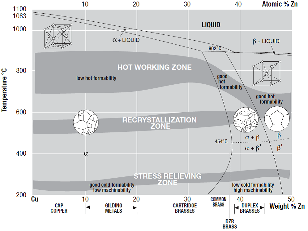
Figure 1 provides a partial phase diagram for a Cu-Zn binary system. Depending on the composition, brass can be divided into three categories (each with a different crystal or grain structure): α brass, α + β brass and β brass as indicated on the phase diagram.
α brasses are soft and ductile, which makes them easy to deform by rolling, bending, drawing spinning, etc., into various functional shapes. Generally, α brasses are hardened by cold or hot working, and then annealed to relieve excessive stress.
Brasses with both α and β phase in their microstructure are termed as α + β brass or ‘duplex brass’, and the volume ratio of the two phases depends on the zinc content. Although β phase has a higher hardness, and therefore reduces cold ductility in α + β brass compared to α brass, it greatly increases the brass’ amenability to hot working by extrusion or stamping, and also enables die casting without hot cracking[3] .
For hot stamping, the ideal alloys (such as duplex brass) need to have maximum ductility at elevated temperature and can be extruded into bars of complex section, while strength and reasonable ductility should be guaranteed at room temperature to ensure structural integrity.
Generally, compression joints are made by either casting molten brass into a shaped die or by hot stamping ingots into shaped components. During processing or fabrication of brass components by cold or hot working, plastic strain increases strength and hardness of the materials, but also results in high residual stresses. A sufficient magnitude of residual tensile stress can lead to unpredictable distortion during cutting or machining, to hot cracking, or to a phenomenon known as stress corrosion cracking (SCC) in storage or service.
SCC requires three conditions in order to occur:
- A susceptible material
- A sustained tensile stress above a certain threshold
- A specific corrosive species
Brass is susceptible to SCC in the presence of ammonia. It is of note that only trace amounts of ammonia (which can be present in air or sweat for example) is required in order for SCC to initiate.
In the case of compression joints, the stress could be from two sources. The first is an applied stress, whether from the manner in which the parts were connected during assembly, or from the stresses on the joint from installation. The second source of stress could be due to residual stress in the material, generated during manufacture. Brass can be annealed (or heat treated) during manufacture, which has the effect of changing the microstructure of the brass and its mechanical properties. If brasses are not heat treated, then it is possible that they will have retained stress and can fail at lower stresses than they might otherwise do.
In order to relieve residual stresses in brass, and thereby reduce the likelihood of cracking, components should be annealed to relieve internal residual stress without appreciably affecting functional properties[4].
Hawkins have seen in-service components fail due to SCC, which can lead to escapes of water and oil (e.g. Photograph 3).
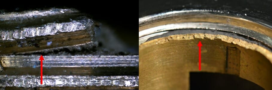
Photograph 3: Examples of failures seen at Hawkins. Left - a threaded stem Right - internal components of a tap.
Left - a threaded stem
Right - internal components of a tap.
At Hawkins, we have carried out testing to examine the composition and grain structure of brass compression joints made by different manufacturers, as well as to examine the level of stress required to cause compression joints to fail while in service. Exemplar joints were made using fittings purchased from the plumber’s merchants, tightened by differing amounts and placed in environments (such as those with high ammonia contents) in order to stimulate SCC. The joints were tested using the methods outlined in both ISO 6957:1988, “Copper Alloys – Ammonia test for stress corrosion resistance” and in ASTM G37 – 98 (2016), “Standard Practice for Use of Mattsson’s Solution [copper sulphate/ammonium sulphate solution]of pH 7.2 to Evaluate the Stress-Corrosion Cracking Susceptibility of Copper -Zinc Alloys”.
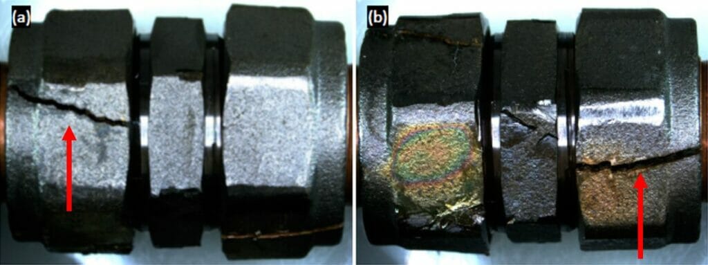
Photograph 4 provides an example of a tightened brass fitting exposed to Mattsson’s solution for 163 hours.
We examined both the microstructure and the elemental composition of each of the brass fittings chosen for examination, which were all duplex brasses. It is interesting to note that the majority of the fittings examined exhibited microstructures that indicated the components had been formed by hot rolling. However, the microstructures did not suggest that they had been heat treated afterwards to relieve residual stress from forming. This suggests that the components we examined would be much more susceptible to SCC at lower stresses than components which had been heat treated (and therefore stress relieved).
Photographs 5 and 6 show cracking in different fittings, which have a visibly different microstructure. It is worthy of note that samples with the same elemental composition can have completely different microstructures depending on cooling rates and manufacturing routes. In each microstructure, the α brass phase is lighter in colour than the β phase. The dark spherical shapes are lead particulates.
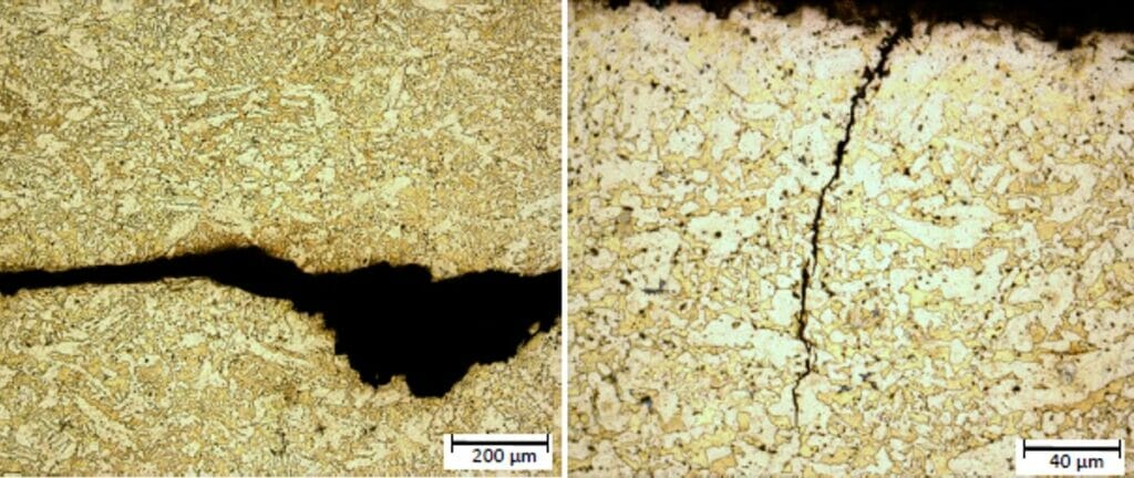
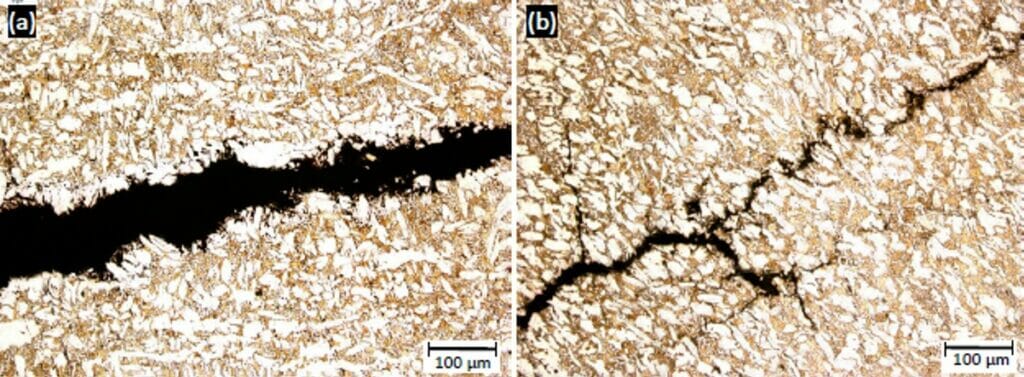
Lead is added to brass to improve machinability, which refers to the ease with which a metal can be cut; the range of fittings examined at Hawkins had lead compositions of 1.8 wt % to 3.0 wt % and it is interesting to note that those fittings with an increased lead content appeared to be more susceptible to SCC. The addition of lead has little effect on the hardness and ultimate tensile strength of brass. However, the fracture energy of brass with an increased lead content is reduced (although the machinability of brass with increased lead content is improved). This is because the interfacial boundary between lead and the bulk is weak, and therefore cracks can propagate along the boundary more easily, thereby assisting crack initiation and propagation at low energies.
Although the increased lead content affected the susceptibility of the brass components to SCC, the tests carried out concluded that the primary factor governing the susceptibility of fittings to SCC was tightening stress. For example, overtightening some brands of fittings by only half a turn was enough to induce cracking at significantly shorter times than if the joint had been made to manufacturer’s instructions.
Interestingly, ISO 6957:1988, “Copper Alloys – Ammonia test for stress corrosion resistance” requires immersion of components in ammonium chloride solution for 24 hours. When the joints were made in accordance to the manufacturer’s guidelines, all the components tested in this study passed this requirement. However, when either immersing the components for longer timescales, or immersing the components in a more aggressive environment (for example Mattson’s solution, as outlined in ASTM G37 – 98 2016, “Standard Practice for Use of Mattsson’s Solution of pH 7.2 to Evaluate the Stress-Corrosion Cracking Susceptibility of Coper -Zinc Alloys”), most of the samples tested failed.
In summary, this study indicates that of all the brass fittings examined, none appeared to have undergone annealing post-manufacture in order to alleviate any residual stress from forming. Therefore, these fittings are more likely to undergo SCC than those that are annealed and stress relieved. The study carried out indicated that the most significant factor to cause SCC in these fittings was the stress induced in the fitting during assembly, i.e. overtightening during installation. Therefore, it is important for any installer to follow the manufacturer’s installation instructions to avoid failure of components by SCC.
ABOUT THE AUTHOR
Dr Eleanor Jay is a Chartered Engineer and Chartered Scientist who has a background in materials science and specialises in material failures. With Hawkins, Eleanor has specialised in investigations of material failures (ceramic, glass, polymers, metals), metallurgy, escapes of water, oil and other fuels, mechanical system failures, and personal injuries.
[1] Image taken from http://www.10weymouth.com/accessible.html
[2] Image taken from http://www.metmuseum.org/toah/images/h3/h3_1990.332.jpg
[3] Callcut, V., revised by Webster P., (2005). The Brasses Properties & Applications. Copper Development Association. Retrieved June 19th, 2017.
[4] Totten, G., (2016). Heat Treating of Nonferrous Alloys, ASM Handbook Vol. 4E. Materials Park, OH: ASM International.


