20 7481 4897")


 Italiano

The concept of Functional Safety is used in designing and specifying Safety Instrumented Systems for the process, nuclear and other industries. This Insight provides an overview of the concept of functional safety, and focuses on how mechanical products are assessed in accordance with the appropriate parts of Standard IEC61508.
WHAT IS FUNCTIONAL SAFETY?
Functional Safety (often referred to as “SIL” or “Safety Integrity Level”) is a way of determining how likely a safety system is to operate correctly when required, (termed as “on demand”). The concept originated as a means of assessing the safety of software-based safety equipment, such as programmable logic controllers (PLCs), and how the availability of such systems could be assessed and quantified. The relevant electro technical standards are as follows:
- IEC61508 parts 1 to 7:2010 - for devices, such as valves, switches, etc.
- IEC61511 parts 1 to 3:2017 - implementation within the process and allied industries
- IEC61513:2013 - implementation within the nuclear industry
Functional Safety serves to reduce risks due to functional errors, in the same way that the PED (Pressure Equipment Directive) and ATEX (equipment for use in explosive atmospheres) directives protect against explosion. Functional Safety is not, at present, a legal requirement. However, it is considered “best practice,” and companies have been fined for failing to adhere to its principles.
SAFETY INSTRUMENTED SYSTEMS
A Safety Instrumented System (“SIS”) is a system which uses instrumentation to both monitor a process and make that process safe if/when pre-set parameters are exceeded. The SIS provides an additional layer of protection for equipment, assets or personnel in the same way that the ABS system on a car provides an additional instrumented system for reducing the chance of an accident.
Let us use the example of a pressurised vessel in a process plant, such as an oil refinery. Figure 1 shows how an SIS would fit into the hierarchy of safety systems for this vessel.
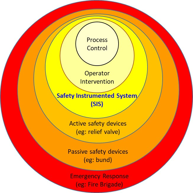
The devices which make up the Safety Instrumented System are referred to as being in the “safety loop”. Functional Safety only applies to Safety Instrumented Systems which have Electrical, Electronic or Programmable Electronic (E/E/PES) content; it does not apply to either supply or control equipment, active or passive safety devices (relief valves, bunds etc.), or devices which require manual intervention, as these form other layers of protection for the process. These stipulations are often misunderstood, and requests are often made to manufacturers for the SIL data of devices which do not appear within the safety loop.
A RISK-BASED APPROACH
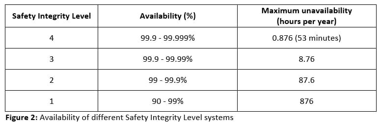
The concept of Functional Safety is to use a risk-based approach to assess the requirement for the availability of a safety system. The process starts with the end user conducting an assessment of the risks presented by a process. For instance, following the above example, this risk could be an over temperature or over pressure event, both of which could then result in a failure of the containment vessel. The assessment provides a target for the system to achieve, and may be dependent upon either the value of the assets involved or the risk to personnel. In the instance of the pressurised vessel example, the consequences of failure would be higher from a personnel perspective if the vessel was located in a residential area, as opposed to on an offshore oil platform. As a result the system is given a “Safety Integrity Level” or “SIL”, ranging from 1 (lowest availability) to 4 (highest availability). In this case “availability” can be considered as the statistical probability of the system operating when required. Generally, if a process requires an SIL 4 system, it is considered too dangerous to implement and an alternative would normally be sought. It should also be noted that minimum figures are required for systems to achieve SIL 1, and therefore if the availability of a system is too low, it will not be awarded an SIL.
HOW CAN SYSTEMS BE DESIGNED TO MEET SIL REQUIREMENTS?
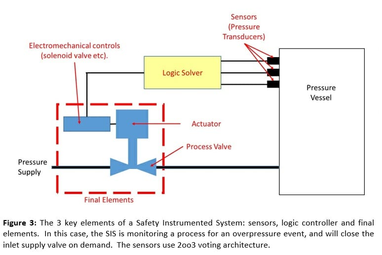
The SIS is made up of a series of devices, such as sensors, valves, etc. Each of these is awarded an SIL capability and calculations can be performed to determine the overall SIL of the system. This can then be compared with the specification to ensure that the system meets the design requirements. An SIS comprises 3 key elements:
- Sensors
- Logic Controller
- “Final Elements”
The sensors may be pressure or temperature transducers (or some other type of sensor), which are used to detect when the process parameters go outside the expected range.
The logic controller is an electronic device that may take the form of a PLC or similar. If predetermined levels are reached by the appropriate number of sensors, a logic controller sends a signal to the “final elements” to reduce the risk.
The “final elements” are often an electrical to mechanical interface, and may take the form of a solenoid valve, mainstage valve, actuator or process valve. These items will usually be designed to fail to a “safe” position in the event of a power loss, which helps to increase the SIL capability of each device (see below).
Let us again consider our earlier example of the pressure vessel. In this instance, the Safety Instrumented System may monitor the pressure within the vessel using a pressure transducer. If the pressure exceeds a pre-determined level, the logic controller will make a decision to close the inlet valve to the vessel, preventing any further increase in the pressure. Note this is in addition to any process control equipment or pressure relief valves fitted to the pressure vessel. If a further parameter, such as temperature, was to be monitored, this would require an entirely separate Safety Instrumented System. Systems are usually designed with redundancy by using, for instance, 3 sensors. The system will be designed to operate if two of these three sensors reach the required level (called 2 out of 3 voting, often written as “2oo3”). This ensures that the system will operate correctly even if one of the sensors fails.
HOW ARE COMPONENTS AWARDED AN SIL CAPABILITY?
An SIL capability determines the maximum system safety integrity level in which a device can operate. Components can be awarded an SIL capability in several ways, according to the relevant parts of IEC 61508. For complex devices where failure modes are difficult to quantify, such as complex electronic items, a fault tree approach can be used. Another approach is to use “proven in use” data from equipment which has been installed in the field. However, the level of rigour required for this data is extremely high, and therefore it is usually prohibitive for businesses to use this approach. More commonly, for simple devices such as valves and actuators where failure modes can be easily determined, a component level Failure Modes and Effects Design Analysis (FMEDA) is conducted. This is a process in which the possible failures of each component are considered along with their effects on the operation of the device. For instance, a shaft bearing may stick, or a seal may leak, and each of these has a probability of occurring per hour of use. An important aspect for this assessment is the safety function of the device; this is determined as the function which the device is required to perform “on demand” (i.e. upon activation of the safety loop). This can have significant implications on the figures obtained; for instance, if a non-return valve is used to ensure a circuit remains pressurised (by closing on demand), then its failure modes will be very different to the failure modes of a valve on the exhaust side of the system (where it will be required to open on demand). It is the responsibility of the end user to ensure that the safety function, against which any devices in such a system are assessed, is appropriate for the way in which the system operates, and therefore that the data are representative.
Once the safety function of the device has been determined, the result of failure of each component of the device can then be assessed to determine if any of the failures has an effect on the safety function. There are three possible outcomes of this assessment:
1. A safe failure is one which returns the valve to the safe position.
2. A dangerous failure is one which inhibits the safety function.
3. All other failures are deemed “no effect,” as they do not instigate or compromise the safety function of the device.
Once again, one of the subtleties of the standard is that a device may fail in a manner which presents a hazard (for instance, an escape of hydraulic fluid). However, in the context of the safety function, this may still be a “safe failure”. The failure modes and associated probabilities of failure (in failures/hr) for each component are taken from commercially available databases for the component type under analysis.
A “Proof Test Interval” also has to be specified; it is customary for this to be one year, less one working day, for maintenance, expressed in hours. Practically, this means that the safety system has to be tested annually to ensure that it functions as intended. Theoretically, once the system has been tested the probability of it operating correctly when required is increased. This then reduces over time, up to the point of the next proof test when the cycle is repeated.
Once each component has been assessed in this manner, two figures are calculated in accordance with the standard from the probabilities of failure. The first figure is the “Probability of Failure on Demand” (PFD), which is in effect the probability expressed as a rate per hour, in which the device would be “unavailable” (i.e. would not perform the required safety function). This is calculated from the sum of all of the failure rates that have been attributed to “dangerous” failures in the assessment, divided by the proof test interval in hours, such that it is expressed as a probability of failure per hour. The second figure is the “Safe Failure Fraction” (SFF), which is the ratio of the probabilities for failures that have been attributed as “safe”, relative to the total probabilities of all safe and dangerous failures determined in the assessment.
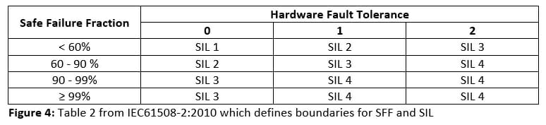
Table 2 of IEC61508-2, reproduced in Figure 4, provides boundaries for allowable SFF levels in each SIL capability (PFD is defined in a similar way as per Figure 1). The lower SIL capability level derived from the PFD and SFF determines the SIL capability of the product design.
Another factor used in determining the SIL capability of a device is the “Hardware Fault Tolerance” (HFT). This is a measure of “redundancy” from using several devices connected together, which allows an increased SIL capability to be claimed. The hardware fault tolerance awarded is equivalent to the number of redundant devices (i.e. an HFT of “0” means no redundancy, an HFT of “1” means 1 redundant device, an HFT of “2” means 2 redundant devices, etc).
Additionally, organisations which design and manufacture devices must exhibit systems which are suitable for the design, development, testing and manufacture of robust products. IEC61508 details the required “techniques and measures” (methods) which an organisation must use (such as project management, computer modelling and environmental testing) in designing and evaluating a product with a safety function. Depending upon the techniques and measures used to develop and build the device, a “Systematic Capability” (often termed “SC”) can be determined for the business.
It is the lower level of the Systematic Capability and the Product Design which determines the overall SIL capability of the device.
The level of independence of the assessor also limits the SIL capability that can be determined for a device. The higher the level of independence (for instance conducted by a 3rd party rather than the device manufacturer), the more rigorous the assessment is considered.
SIL capability figures including PFD, SFF and HFT are often presented in the form of a certificate for convenience; however, there is no requirement in any part of IEC61508 for a certificate, and therefore formats can vary. Capability figures should be carefully checked to ensure that the content is understood and that the values, including overall SIL capability for the product, have been correctly identified. Devices that have been assessed against IEC61508 must also be supplied with a safety manual, which defines the safety function of the device along with proof test information and fault conditions.
The overall SIL for the SIS can then be calculated by application of the relevant parts of IEC61511 or IEC61513.
In summary, the application of functional safety to devices contained within emergency systems ensures that such systems are designed to provide a high level of availability, and if a failure does occur this is ‘safe’ with respect to the safety function. The standard IEC61508 can be applied to devices in order to assess their SIL capability for a given safety function.
ABOUT THE AUTHOR
James Kingham is a Chartered Engineer (CEng) and a member of The Institution of Mechanical Engineers (IMechE). James graduated with a MEng in Mechanical Engineering from the University of Birmingham in 2005, and has worked in the aerospace/defence industry on high pressure gas systems and cooling systems for infra-red seekers. James has also worked on the design and development of products for hydraulic and pneumatic systems used in valve actuation and control applications, primarily in the offshore oil and gas and rail industries. Since joining Hawkins in 2017, James has conducted many Road Traffic Accident (RTA) and engineering investigations, specialising in accident reconstructions and vehicle fires.