20 7481 4897")


 Italiano
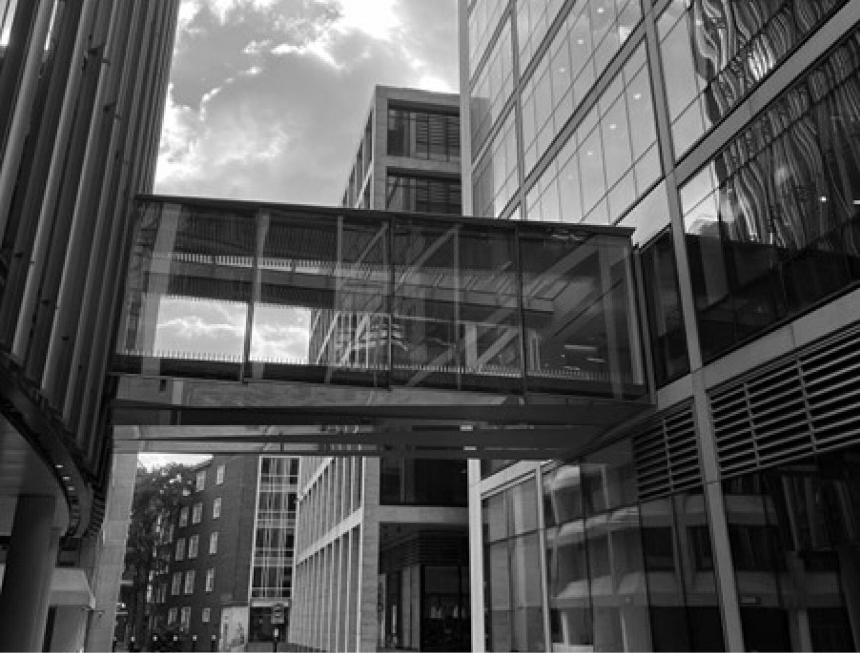

Finite movement under load or changing environmental conditions is an inescapable phenomenon in any structure, due to its finite stiffness. The design team must ensure that the movement of the system, guided by “wished in place” design, has no unforeseen consequences in terms of structural and aesthetic performance over the design life. As well as considering construction practicalities and operations and maintenance, they must address deflection criteria and joint provision to ensure structural integrity. This is essential for accommodating movement in structures and facades.
Movement of a structure or façade, either vertical or horizontal, can occur due to several factors:
Direct Loading:
- Live
- Wind
- Snow
- Seismic
Environmental conditions:
- Temperature variation (thermal)
- Change in humidity/moisture levels and absorption of water
- Chemical action
Age-effects:
- Creep
- Shrinkage
- Dynamic relaxation
Support Movement:
- Differential settlement
- Subsidence
- Variation of soil properties
DEFLECTION CRITERIA
Deflection criteria, generally quoted as a function of height or length of an element, must be established during the design of any structure. These may be to limit visual perceptibility of deflection, control occupant comfort or to avoid damage to non-structural elements and cracking of structural members. They are considered in the design alongside stress limits of a material.
Whilst codes of practice and regulations may give guidance on appropriate deflection criteria, these are not as fixed as stress limits and may be considered on a case-by-case basis. For example, the detailing of a façade system may often impose tight deflection limits on the primary structural frame of a building. In addition to maximum absolute deflection, relative deflection between adjacent storeys should also be limited.
It should be noted that frequently these “serviceability criteria” are not the limiting factor, since member strength may be more critical, especially for low-rise structures and shorter elements.
PROVISION OF JOINTS
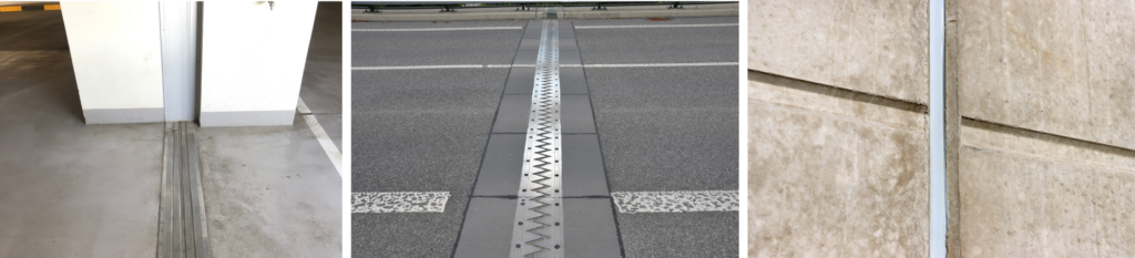
Within buildings, bridges and façade systems of any significant size, the designer should consider providing appropriate joints to accommodate the expected movements and material expansion discussed above. Examples can be seen in Photographs 1 to 3. The following terms are frequently used:
Movement (or isolation) joints will effectively split what appears to be a single structure into multiple independent structures, each of which therefore requires its own independent stability system.
Expansion joint – a partial (or full) isolation joint in concrete through which reinforcement may be partially or fully interrupted to allow for expansion of the material.
Construction joints – interface between sequential pours of concrete, generally without impact on the final structure
Contraction joints – grooves cut in concrete to give surety regarding the formation of cracks in concrete as it shrinks with time.
JOINT DESIGN
The following considerations should be addressed in designing joints:
- Appropriate spacing and location
- Required width for expansion and contraction
- Construction tolerance, i.e. permissible deviation from the specified width at the time of construction and how deviation is accommodated
- Sealing of joints, as required
- Consequences of joints, e.g. vertical movement across a joint creating a trip hazard
- Access for inspection of joints and possible replacement of sealant
BS 6093:2006 Design of joints and jointing in building construction (Clause 4.1) notes that “since joints are breaks in the physical continuity of construction, they are potential breaks in the continuity of performance. It is therefore important that an entire assembly, including the joints, should achieve the desired performance.”
With respect to joints in the building envelope, the same code notes “Joints might need to be constructed to obstruct the passage of any or all of the following:
- insects and vermin;
- plants, leaves, roots, seeds and pollen;
- dust and inorganic particles;
- heat, light, sound, radiation;
- air, gases and odours;
- water, snow, ice and water vapour;
- joints might need to avoid the generation of sound and odours.”
Additionally, vertical movement across a joint in a floor slab or roadway should not present a trip hazard for pedestrians or sharp lip to vehicles.
Joints may be filled in various ways, depending on the performance requirements, but should generally be soft, durable and allow high strain. Sealants, such as silicone, may be bonded to the components on either side of the joint. Gaskets, of rubber or other materials, may also provide a barrier, but must remain in compression for their performance to be maintained. Such components generally have a significantly shorter design life than that of the structural elements. Means and frequency of inspection should be defined in an Operations and Maintenance (O&M) manual, which should be followed to reduce the risk of performance being compromised.
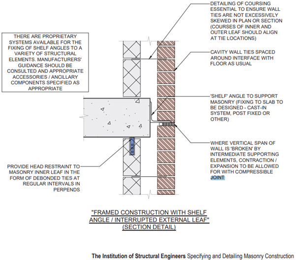
Figure 1 shows considerations for jointing of masonry façade to allow the brickwork to move with the supporting slab at each floor level but to expand and contract independently.
RESTRAINTS TO SUPPORTED ELEMENTS
Various elements may be supported by the main structure(s)
of a building or buildings. Examples
include:
- Façade elements such as brickwork or rainscreen cladding
- Glazing
- Bridging Elements
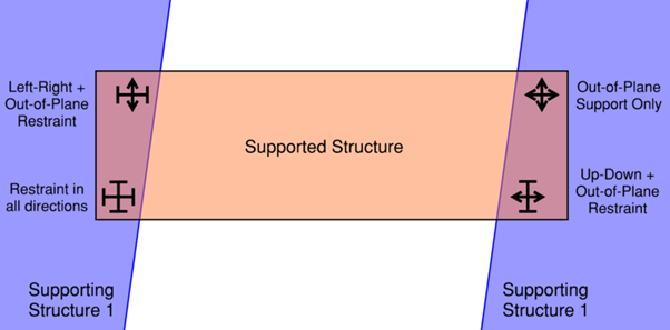
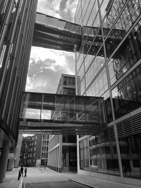
Anything bridging between independent supports must have adequate restraint to prevent free movement or rotation in any direction, without tying the supports together and hence avoiding being loaded by their relative movement. A typical arrangement is shown in Figure 2 for a conventional bridging structure. Photograph 4 shows link bridges spanning between supporting buildings in Central London, adopting this support system, for which the author was the lead structural engineer.
A façade panel or internal partition may be considered “bridging” between floors of a building, with adjacent floors subject to differential vertical deflection. For this reason, vertical supports should only be provided within one floor, ideally at only two points to provide certainty of load distribution.
Cladding assemblies are typically exposed to very different environmental conditions to the main structural frame that supports them. The structural frame is generally under stable and regulated internal conditions, whereas cladding is exposed to extremes of temperature, humidity and thermal radiation. Supports to cladding must therefore be designed to accommodate changes in the external conditions.
WHAT CAN GO WRONG?
There are numerous factors to consider with regards to accommodating movement and hence many things can go wrong. These may arise from:
- Poor pre-construction coordination and specification within the design team, resulting in inappropriate joints
- Construction errors, such as excessive deviation from designed dimensions or incorrect materials used
- Insufficient joint inspection frequency with degradation not being identified
- Damage to sealant from impact, abrasion, weathering, chemicals, incompatibility with substrate, or failure due to excessive movement
- Building services infrastructure not detailed to allow for movement across a joint, resulting in damage to these services
- Rigid material compressed between joints
The above factors can lead to:
- Load transfer between independent structures causingf failures
- Water ingress
- Excessive air permeability
- Inadequate fire resistance
- Loss of thermal/acoustic insulation
- Corrosion damage to internal fittings/finishings
- Excessive friction on sliding interface
CONCLUSIONS
There are many potential issues relating to building movement and ensuring the appropriate performance of movement joints can be complex. Communication and coordination between members of the design team and with the client is essential in achieving an end product that is acceptable for all.
Hawkins’ Built Environment team can assist in the investigation of any physical defect or damage associated with design, construction and operation of movement joints. Our Architects and Engineers have the capability and experience to assess whether the coordination between members of the design team, which is of paramount importance, has been carried out to a reasonable standard.
If you are dealing with a related incident and want to know what has caused it and how to prevent the same thing happening again in the future, Hawkins can provide an expert who is familiar with all aspects of a case and can offer clarity and answers to your questions.
In addition to investigating failures, we are often asked to review designs on a proactive basis, in order to prevent future problems. This provides our clients with confidence that their buildings or structures are sound.