20 7481 4897")


 Italiano

In 2021, it was reported that domestic escapes of water claims had risen by 30% in the first quarter of the year, reaching a total value of £175m¹ Other industry bodies ² ³ report that the total cost of escape of water claims is now in the region of £2.5m every day, presumably taking into account losses that occur in both domestic and commercial premises. Zurich reports that this figure is currently increasing, driven by both a rising frequency of incidents and a significant increase in the average cost of claims.
Hawkins has investigated numerous escapes of water in both commercial and domestic premises where the cause has been identified as either: poor workmanship (I.e. incorrect installation); defective fittings; or environmental factors, such as ice formation or corrosion. However, one of the more obscure and interesting failure mechanisms identified by investigators during escape of water investigations is hydraulic shock, more commonly referred to as ‘water hammer’, particularly in tall buildings. Whilst not necessarily always identified as the root cause, investigators must always consider the potential influence of hydraulic shock on the plumbing installation.
WHAT IS WATER HAMMER?
Water hammer is a phenomenon that most people have encountered at some point or another, although they may not have been aware of it. Sometimes referred to as pressure surges or transient flow, water hammer occurs due to sudden changes in the flow and pressure within a plumbing system.
Within domestic installations, these changes can be generated by operating quick-closing valves such as quarter-turn taps, or by solenoid valves in washing appliances (dishwashers, washing machines etc.). Under these circumstances, water hammer is often characterised by the banging or movement of pipes. While a single water hammer event may not be sufficient to rupture the pipework or adjoining fittings, successive water hammer events may lead to eventual catastrophic failure, resulting in an escape of water.
In commercial plumbing installations, which often incorporate large diameter pipework and pumped systems, water hammer can be a single destructive event that occurs when a pressure wave rapidly propagates through the pipework; a pressure wave can be severe enough to rupture the pipeline. For instance, in pumped systems, the instantaneous shut down of the pump can generate a pressure wave that propagates through the pipework. This pressure wave causes the temperature at which the water within the pipe turns to vapour to reduce significantly, at which point cavitation can occur within a long part of the pipe. As the resulting cavity then collapses, a high-pressure wave advances along the pipe which can damage the pipeline and cause the fittings to fail.
Another particularly dangerous, and increasingly common scenario, is when the pump in a boosted cold-water system is shut down, either accidentally or deliberately. The building’s riser becomes partially drained down, and this when a valve(s) is opened at the base of the riser or when taps are opened on lower floors, a cavity forms at the top of the pipework, at a pressure that is less than atmospheric pressure (i.e. a partial vacuum), due to the fact that the remaining column of water is essentially suspended from it.
When the pump is re-energised, if steps are not taken to limit the rate at which water is reintroduced to the system, the suspended column of water can be accelerated rapidly towards the top of the column (with little resistance due to the presence of the partial vacuum cavity at the top of the riser). The cavity rapidly collapses, resulting in considerable force being exerted on the pipework and fittings as the column collides with the top of the riser and then reflects a pressure wave back down the riser and into the pipework that branches from it. The magnitude of the incident and the reflected pressure waves can sometimes exceed the rated operating pressures of components within the plumbing system. However, the infrequent occurrence of catastrophic component failure suggests that there might not be sufficient energy within the pressure waves to cause such failures. Importantly, the pressure surges can, and frequently do, exceed the pressure that pipework joints have been tested to withstand during commissioning. Surges can typically exceed 1.5 times the normal system operating pressure.
LABORATORY TESTING
To demonstrate water hammer in a vertical water column, Hawkins designed a test apparatus with a vertical translucent water column connected to a hydraulic piston and pressure vessel. A digital pressure gauge is connected to the top of the water column, which is capable of measuring both negative pressure within the column, as well as recording instantaneous maximum pressure values.
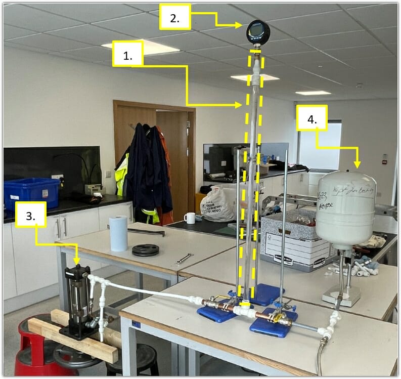
Tests were carried out with initial system static pressures of 2, 4 and 6 bar, with the latter being typical of the pump pressure setting on boosted cold water systems. The pipework at the base of the water column was isolated from the water supply, to simulate the shutting down of booster pumps, and was connected to a hydraulic cylinder. Weights were added to the piston to simulate the mass of water suspended in a pipework riser, such as those typically encountered in tall buildings.
With the addition of the weights, the piston was drawn from the cylinder, simulating the drawing off of water from the base of the column, which would occur in a full–scale installation due to the positive water pressure that would still exist at the base of a tall column.
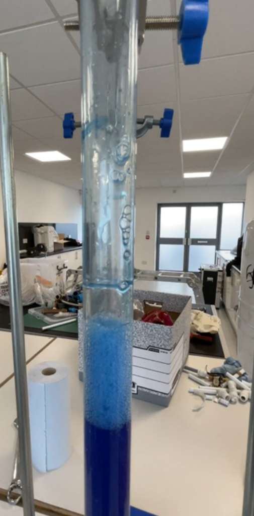
The movement of the piston resulted in the formation of a cavity at the top of the water column as shown in the image below. It is important to remember that rather than being a void that is filled with air at atmospheric pressure, the free space at the top of the water column is instead at sub-atmospheric pressure; i.e. a partial vacuum and is therefore free to collapse with little resistance.
During each test, once the cavity had formed, the cylinder was isolated from the water column, but the partial vacuum cavity remained at the top of the column.
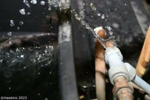
The second phase of the test was to reintroduce a pressurised water supply to the water column. This was achieved by the rapid opening of a quarter–turn valve that connected an accumulator vessel, which was pre-charged with air and water at the prevalent static system pressure (2, 4 or 6 bar) to the base of the water column. The opening of the valve resulted in the rapid inflow of water to the pipework and the equally rapid collapse of the cavity at the top of the column, accompanied by an associated transient spike in pressure. The following short video shows the collapse of the cavity, the accompanying characteristic water hammer ‘bang’, and the vibration of the vertical pipe.
Pressure surge in the water column.
The testing demonstrated that in a 22 mm diameter pipe, pressure spikes of up to 25 bar were recorded with an initial system pressure of 6 bar. These results demonstrate that under laboratory conditions, pressure surges of more than 4 times that of the normal operating pressure of the system were generated within the water column. Importantly, for a design system pressure of 6 bar, static pressure testing undertaken during commissioning would typically have been carried out at 9 bar.
Whilst 25 bar would not be expected to cause the catastrophic failure of many plumbing fittings, this small-scale testing demonstrates the potential for the pipework in tall buildings to be subjected to transient pressure surges. Those surges include forces well above the pressures to which the system will have been tested during commissioning. Exposing pipework to such pressures presents a risk that poorly assembled joints, previously thought to be mechanically sound, will separate. This separation failure mode typically occurs in escapes of water associated with this type of incident
PREVENTING WATER HAMMER IN VERTICAL WATER COLUMNS
To prevent the development of cavities and, consequently, the generation of high pressure surges within vertical pipework, devices such as a surge tank or a combined anti-surge, anti-vacuum (CAVSA) valve can be incorporated into the plumbing installation. Surge tanks operate similarly to a shock absorber in a car suspension system, by using the compressibility of air to dampen the effects of any pressure surge. However, their use is typically associated with horizontal pipework. CAVSA valves, on the other hand, are often installed at the top of water columns and allow air to enter the plumbing installation in the event of unintended partial drain-down during pump outages. These valves prevent a vacuum from forming at the top of the column. The air introduced also acts as a cushion to slow the advancing water column and minimise the transient pressure spike. Once the transient has passed, the valve allows the air to bleed from the system, but prevents the loss of water.
Hawkins often encounter situations where CAVSA valves, though installed, have been left isolated by the placement of a closed valve between them and the riser pipe that leaves the valves unable to serve their intended function. This oversight in installation is almost certainly due to a lack of understanding by those involved in both the installation and the inspection of plumbing systems. The installation of CAVSA valves requires knowledge of not only the purpose of the valves, but also the underlying issue that they are intended to address.
INVESTIGATING CASES INVOLVING WATER HAMMER
Hawkins investigates hundreds of escapes of water cases every year, including those where pressure surges are thought to have contributed to the failure. We can undertake on-site investigations to inspect the plumbing installation to establish whether or not a pressure surge is likely to have occurred. If this is the case, Hawkins’ investigators can obtain additional background information from witnesses and other associated parties to establish why pressure surges in the pipework may have occurred.
ABOUT THE AUTHOR
Dr Tom Peat is a Chartered Engineer and a member of the Institution of Mechanical Engineers (IMechE). Tom graduated with a MEng in Aero-Mechanical Engineering from the University of Strathclyde before returning to complete a PhD in Advanced Surface Engineering within the Department of Mechanical and Aerospace Engineering. Since joining Hawkins in 2017, Tom has investigated numerous commercial and domestic fires, escapes of water and oil, and engineering cases.
¹https://www.zurich.co.uk/-/media/news-and-insight/documents/usefuldocuments/the_increasing_severity_of_housing_escape_of_water_losses.pdf
²https://www.watersafe.org.uk/blog/posts/water_pressure_tackling_escape_of_water/
³https://nig.com/trading-support/news/your-guide-to-escape-of-water-full-article/#_edn1