20 7481 4897")

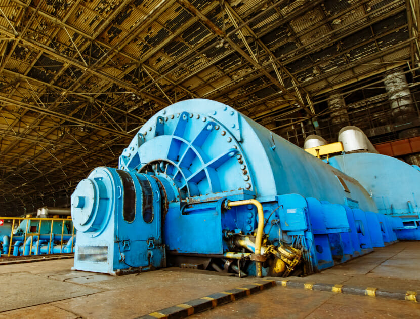

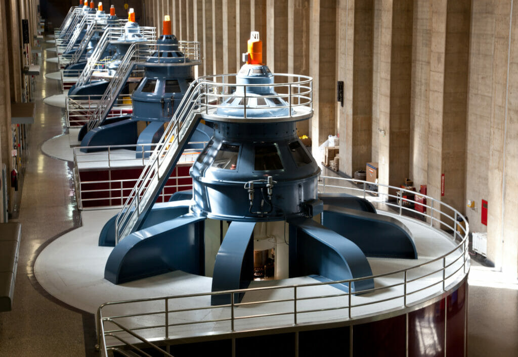
The process of turning mechanical energy into electrical power is pretty fascinating. You may remember turning a magnet near a coil and seeing a light bulb illuminate at school? In practice, power generation in the real world is fairly similar; an electromagnet is spun by a turbine (through wind, water, steam or a combustion engine) and power is produced. In practice, this electro-magnet may be over 100 tonnes, spinning at 3000 times a minute within a stationary coil weighing hundreds of tonnes. The largest generators being manufactured at the moment are rated in excess of 1.5 GW (gigawatts, or billion watts – enough to power three million UK homes). Whether being driven by wind, water steam or gas turbines, all generators are made of the same parts. To understand generators a little better, there are three major components to be aware of:
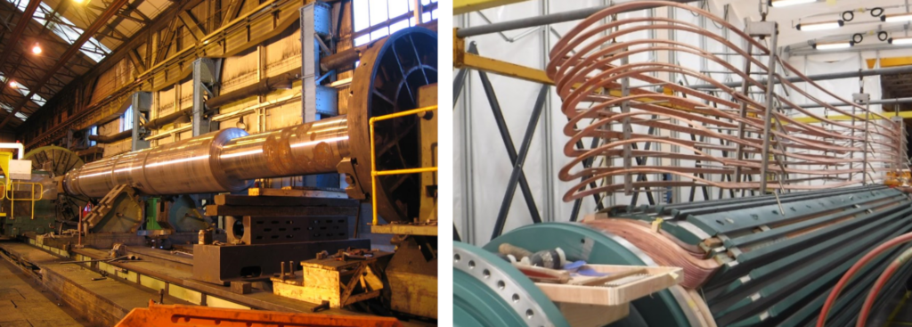
THE ROTOR
This is the rotating electromagnet. On a large, high speed turbo generator, the rotor is machined from a large steel forging, which has slots cut into it, into which copper windings are wound. These windings are then fed from an external DC supply, which creates a large electromagnet that will be spun within a stationary coil (stator).
THE STATOR
This is effectively the stationary coil of wire in the aforementioned school experiment. In actuality, large copper conductors are wound into three phases in an annulus, or ring, around which the electromagnet rotor spins.
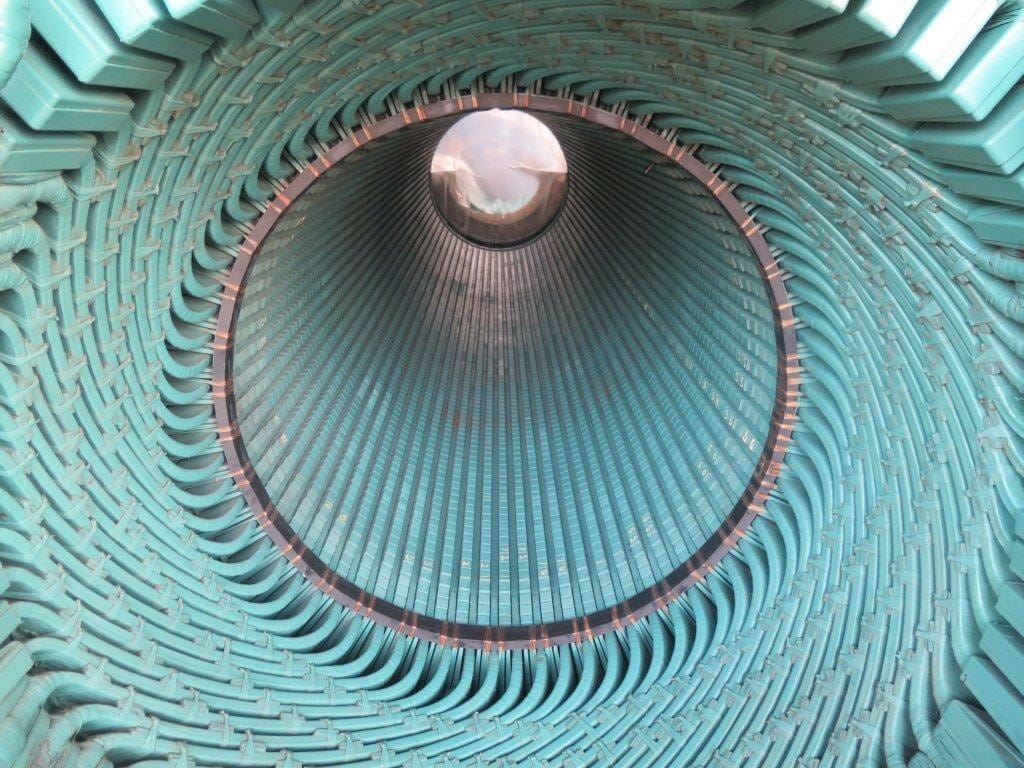
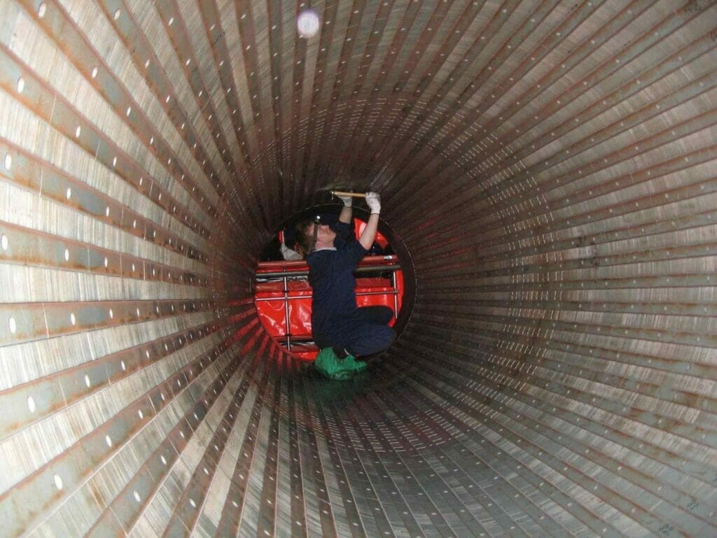
THE CORE
The stator windings are wound into slots within the stator core, which is constructed of thousands of thin (approx. 0.5mm) laminations of steel that are all insulated from one another. This core, in simple terms, along with the steel in the rotor, provides a path for a magnetic circuit between the rotor and stator.
Most power plant generators spin at the grid frequency, which is 50 Hz in the UK and most of the world (equivalent to 3000 revolutions per minute – RPM), although other countries (such as the US, Brazil, Japan or Saudi Arabia) operate at 60 Hz (3600 RPM). If the generator rotor is spinning at 3000 RPM, the north and south poles of the electromagnet are passing the coils of the stator once per cycle.
Depending on the nature of the turbine, it may be better to operate it at a lower speed; to do this, you can either connect the turbine to the generator via a gearbox, or build your generator rotor with more poles. For example, if you had four poles (two north and two south), you would only have to spin your rotor half as fast in order to produce electricity at the grid frequency – i.e. a four pole machine operating at 1500 rpm would still produce the same effect as a two pole machine operating at 3000 rpm.
Gas turbines, and most steam turbines, work best at higher speeds, so they generally operate at the grid frequency with two pole generators. Wind turbines and hydro power stations will sometimes work better at a far lower speed, and in these cases may have a large number of poles. For example, a hydro generator rotor may have 40 poles (thereby spinning at 150 rpm) or a wind turbine generator may have as many as 96 (spinning at 62.5 rpm).
The largest two pole turbo generators on thermal power plants at the moment are in the region of 1.2 GW. Four pole generators operating at lower speeds are subjected to lower forces and can therefore be built a bit bigger, and the largest generators currently being produced for the new generation of nuclear power stations are rated at 1.6 GW. Hydro plants can have ratings up to around 800 MW, while current wind turbines are now in the region of up to 12 MW.
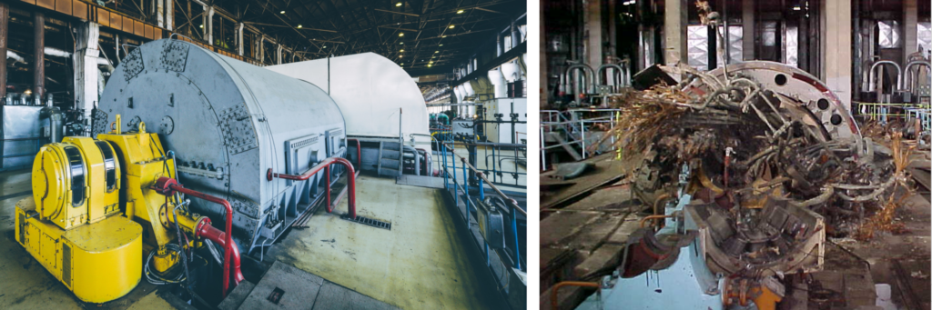
The impact of a loss of a generator can be catastrophic; the property damage is likely to be extensive, but the business interruption can be astronomical. The generator is a piece of equipment without any redundancy and, because of both its size and complexity, the power company will rarely have any spares. Damage to either a stator core or a rotor can, in many cases, lead to a downtime of over year with property damage into the millions. Two years of downtime is also not unheard of.
WITH GREAT POWER COMES GREAT RISKS
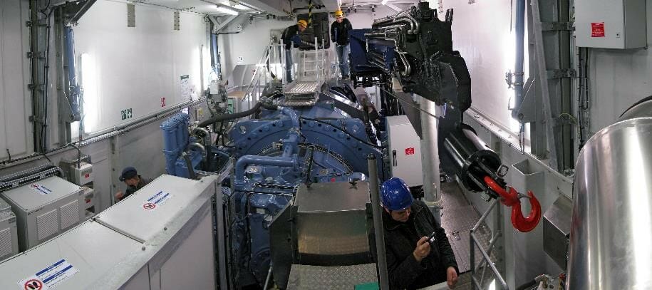
Generators are large pieces of machinery, operating at high speeds, high voltages, and high currents. Designers of these machines have to balance these design factors along with commercial constraints in order to produce economical, safe, and reliable machines that would normally be expected to have a life of around 25-40 years.
High speeds
The generator rotors have to have a high level of mechanical integrity. A rotor spinning at 3000 RPM and weighing over 100 tonnes will contain a huge amount of kinetic energy. A mechanical failure of a rotor will have catastrophic consequences to the generator, turbine, and civil structure of the power station.
The rotors are constructed usually from one-piece steel forgings, which are machined and slotted so that the coils that form the rotor windings coils can be wound into the rotor. The coils have to be insulated from the steel and held in place by wedges and retaining rings to prevent the copper from bursting away from the rotor due to the centrifugal forces.
Once constructed, the rotor will have to be finely balanced in order to keep vibrations low; this is a complicated process as the rotors are long and thin and their dynamics will change depending on both their speed (as they run up and down) and their electrical loading (as the copper windings heat/cool and expand/contract relative to the steel forging).
High Current
High current presents a number of difficulties for the designers of generator. First, high current will create lots of heat. The waste heat created by the rotor and stators can be several megawatts (enough to power 1000s of homes!). If this heat is not removed quickly, the generator temperature will rise, burn the insulation, and eventually melt the copper.
On large machines, the generators will be encased in pressurised hydrogen. Hydrogen has a greater capacity than air to remove heat from the copper, and also causes less windage (i.e. less resistance to the movement) as the rotor spins around. However, the problem with hydrogen is that it is a very explosive gas. Although you can build larger generators by using hydrogen, more effort is required to design the plant safely, and more robust procedures and competent operators are also required to reduce the risk of either leaks or explosions.
Whilst hydrogen helps to an extent, for the largest generators, the stator coils will require direct water cooling, where tubes of cooling water are passed directly through the stator copper conductors. Although this provides very efficient cooling of the copper, you will be aware that water and electricity do not always mix. The water chemistry needs to be carefully controlled to ensure it has a very low conductivity to prevent an electrical short circuit and flashover through the water circuit. There are also other potential issues with internal corrosion of the water circuit, which can lead to fouling and blockages.
The heat produced by the current will also cause thermal expansion. Generators can be many meters long, and the conductors will grow a few millimetres between being off (cold) and at full load. As the copper heats, it will expand relative to the steel stator core or the rotor forging (which has a lower coefficient of expansion). This relative movement between the components will stress the insulation between the copper and steel, and over the years of operation, will fret and wear away the insulation and, in some cases, lead to a ratcheting effect, deforming the copper or pushing the insulation out of position and eventually lead to a flashover.
The other effect of having high currents is that current produces a magnetic field, and these magnetic fields will interact with each other. On the stator winding, these forces will act to attract and repel the conductors twice for every cycle of the AC waveform – i.e. 100 times a second in the UK with a 50 Hz grid system. These forces will require the generator structure to be held together tightly, and looseness will reveal itself quickly as the conductors start to move relative to each other and fret away their insulation. This electromagnetic interaction can be made worse if parts of the generator have a mechanical resonance at 100 Hz, as the structure could potential be excited by this as well as the action of the rotor spinning and lead to larger vibrations, including the phenomena of vibrations within the endwindings of the stator (‘Endwinding vibration’).
High Voltages
The voltages on the rotor are relatively low and of the order of a few hundred volts. However, within the stator, the voltages are usually in the order of 11 kV to 27 kV. Higher voltages can cause more complicated problems, such as partial discharges, which will degrade the insulation over time.
Most of these problems are contradictory. High voltage requires thicker insulation, but that then also thermally insulates the conductors. The heat created could be reduced by using thicker copper to reduce the resistance, but using more copper reduces the space for insulation and steel (required for the magnetic circuit). The magnetic interaction between the bars requires that components are held tightly together, but the thermal expansion requires the conductors to be able to move within the steel. Hydrogen and water provide more efficient cooling, as well as enable larger generators to be constructed, but both also bring additional (considerable) risks.
In order to operate a generator safely, or even perform root cause analysis following a failure, expert knowledge is required. Engineers who specialise in generators are therefore required to have a breadth of experience, in not only electrical engineering, but also a wide range of other disciplines, including metallurgy, control systems, mechanical engineering, chemistry, explosive atmospheres and process safety.
ABOUT THE AUTHOR
Ben Adams is a Senior Associate and electrical engineer in
our London office. Prior to joining Hawkins, Ben worked for a number of power companies providing technical support on ‘heavy’ electrical equipment, including failure investigation of generators, transformers, motors and switchgear across the world.