20 7481 4897")


 Italiano
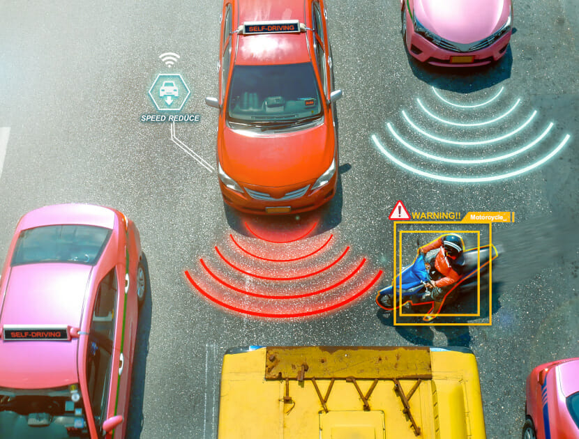

Autonomous Emergency Braking – An Insight Into Test Vs Reality. There is a common misconception among drivers that active safety systems, such as Autonomous Emergency Braking (AEB), will work under all conditions and always avoid collisions. In reality, this is simply not the case. Much in the same way that a human driver has a perception response time, or ‘reaction time’, in circumstances which may lead to a collision, a vehicle’s active safety systems also need to detect an object, perceive what it is, and decide on a course of action.
In the real world, there are parked cars, pedestrians, cyclists, items of street furniture, and road markings, as well as other traffic. In the world of Advanced Driver Assistance Systems (ADAS) testing, including testing for AEB, all aforementioned objects are removed. For example, EuroNCAP is a well-known assessor of new cars and includes a wide variety of active safety elements, along with the more traditional passive safety (crash test) elements.
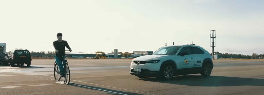
During test programmes, soft target cars and vulnerable road users are used along with intricate instrumentation and motion platforms in order to meet the requirements of each test scenario. Soft targets allow contact between the test vehicle and target to occur, whilst ensuring damage is minimised. A wide range of test scenarios are conducted during a EuroNCAP AEB test programme, with the vehicle’s performance contributing to its overall star-based rating. The current areas covered are car-to-car (C2C) and vulnerable road user (VRU), which involves pedestrians and bicyclists.
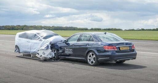
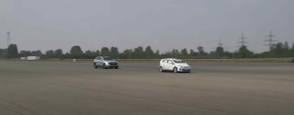
Figure 2 illustrates a Car-to-Car Rear (CCR) test. It can be seen that the test is being conducted in a wide open area, which is free from any other objects, with the soft target car as the only object in close proximity to the test vehicle.
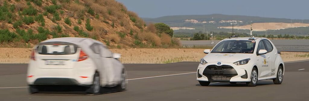
A Car-to-Car Front turn-across-path (CCFtap) test, as illustrated in Figure 3, is conducted on a EuroNCAP specification junction, whereby the test vehicle is steered into the path of an oncoming vehicle, as if it is turning across its path. As in the test above, there can be no other objects in the vehicle’s path. This particular test scenario was introduced in 2020, and at time of writing only eleven cars had been rated based on this specific scenario. It was only in 2014 that AEB was first rated by EuroNCAP and since then the scenarios have increased in complexity to this being the most complex car-to-car scenario there is to date. Prior to EuroNCAP’s 2020 protocols, all AEB car-to-car tests were conducted approaching a soft target car from behind (CCR as above), in a shunt type collision.
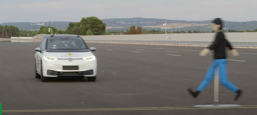
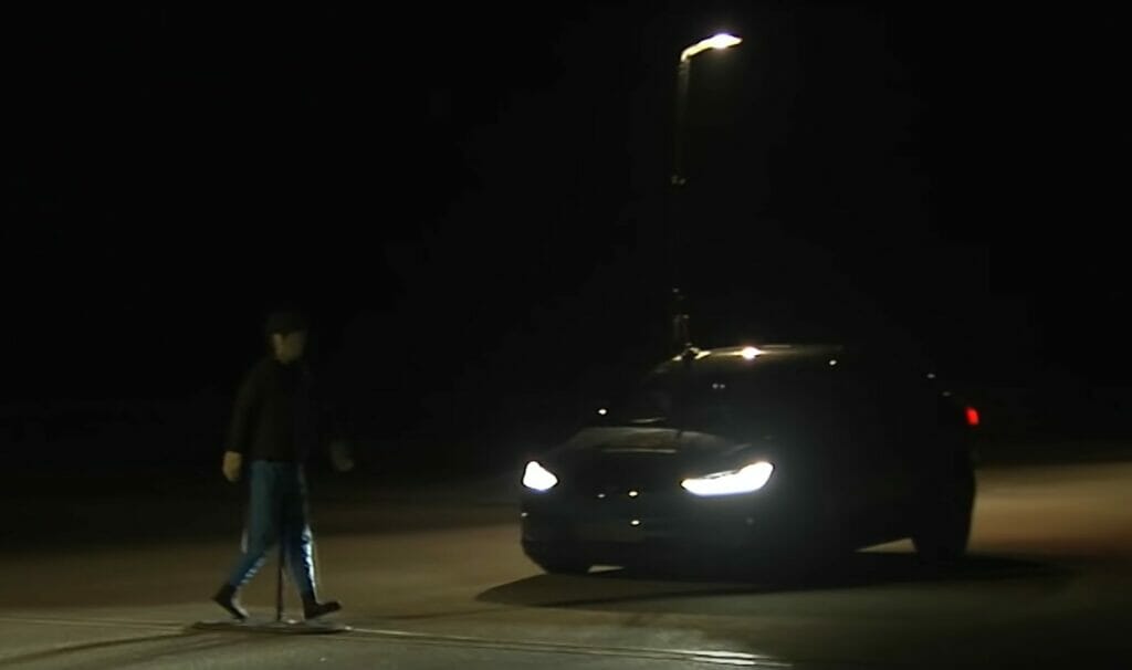
The majority of the VRU scenarios are also conducted during daytime, although there are a small number that are also conducted at night. Of a total of 16 VRU scenarios, only 4 are repeated at night. Figure 4 and Figure 5 are examples of VRU pedestrian and bicyclist test scenarios respectively, whilst Figure 6 is an example of a night-time test. As with car-to-car tests, there is a specified free field in the area in which the test is conducted.
An emergency braking system may work perfectly on a runway (which are areas typically used by a wide range of test service providers) and avoid a hypothetical collision in most instances. However, when the car is driving down a busy road, with a lot of traffic, street furniture, cyclists, and pedestrians, there is no guarantee that the system will act in the same way. A human driver will scan their surroundings for several factors that may affect their driving, including crossing pedestrians, cars pulling out of junctions, children on scooters, and other objects that may cause them to take emergency action to avoid a collision. An active safety system has to do the same, with the algorithms in the system being critical in determining what potential hazards are in the same area, as well as how to act accordingly.

For C2C assessments of AEB under EuroNCAP conditions, the maximum test speed is 80 kmh-1 (50 mph). For VRU’s, this maximum speed is 60 kmh-1 (37 mph). In city and inter-urban areas, these speeds should be sufficient, although at the national speed limit on British A-roads and motorways, the speeds experienced in reality are higher.

Weather is another key factor in the performance of current active safety systems. Temperature, precipitation, visibility, wind, and illumination are all factors that are specified and recorded when tests are conducted in accordance with EuroNCAP protocols. For example, there can be no falling precipitation, while a dry surface should be used, and the natural lighting must be homogenous. According to Statista, it rained on 164.6 days in England during 2019. It is somewhat unknown what effect poor environmental conditions have on AEB system performance as results published by EuroNCAP are based on tests conducted in the specified test conditions.
It is safe to say that performance under test conditions is likely to be better than that experienced in reality.
The Society of Automotive Engineers (SAE) has defined six levels of driving automation, as detailed in Figure 9. Up to and including Level 2, the driver is still actively driving the vehicle, while the driver assistance systems are purely supporting the driver. It is only for Level 3 and above that there can be periods during which the driver is not driving themselves, although at Level 3 the driver assistance feature may request that the driver take over control at any time. Only once Level 5 automation is reached will a vehicle be able to drive itself under all conditions.
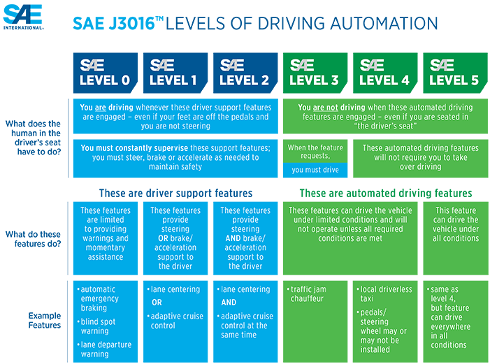
Most ADAS systems are classed as Level 1 systems, whereby the system will only apply one system for avoiding a collision. In the case of AEB, braking is the one avoiding system. There are Level 2 systems available currently. Volvo’s Pilot Assist, for example, will conduct lane centring and adaptive cruise control functions at the same time, although the driver should always be in full control and attentive.
Until forms of full autonomy (Levels 3 to 5) become commercially available, advanced driver assistance systems should remain for their intended purpose: to assist.
ABOUT THE AUTHOR
Robert Taylor has a first class Masters in Mechanical Engineering from the University of Warwick, and a background in automotive test, development, and certification gained whilst working at Millbrook Proving Ground. Whilst at Millbrook, his area of specialisation was Advanced Driver Assistance Systems (ADAS) and he has conducted programmes for a wide range of automotive manufacturers, suppliers, and regulators on a variety of active safety features including AEB, Lane Support Systems, and Speed Assistance Systems.