20 7481 4897")


 Italiano

During 2012, a large five-star hotel and conference centre began experiencing what started out initially as relatively minor escapes of water, which were dealt with easily by the hotel’s in‑house maintenance team. However, during the next two years, the frequency and severity of the leaks intensified. This culminated in a significant escape of water that occurred during a live televised awards ceremony, when the escaping water entered the main electricity supply and distribution equipment, and caused a site-wide blackout.
At the time of this incident, the hotel was seven years old. The water supply to the hotel was derived from an onsite borehole. Water analysis results from when the borehole was commissioned indicated that the water was scale-forming, or ‘hard’, meaning that the water tended to leave scaly mineral deposits on the internal surfaces of the pipework.
The system functioned without issue for approximately five years, after which, the hotel operators unsurprisingly started experiencing problems with scale formation in the domestic water distribution pipework. In order to address this, the hotel staff procured a water softening system, which was installed and commissioned by its vendor. The escapes of water commenced approximately six months after the commissioning of the water softening system.
The hotel engaged the consultant that had originally designed and overseen the installation of the plumbing system to investigate the cause of the escapes of water. Perhaps understandably, the consultant suspected that the installation of the water softening system was at the root of the problem. The vendor of the water softening system was also engaged to sample the water, and he established that the softened water was ‘slightly corrosive’. A bypass that allowed a small proportion of borehole water directly into the main storage tank was installed on the consultant’s recommendation, and it eliminated the corrosiveness. However, the escapes of water not only continued, but also affected pipework that was replaced after the installation of the bypass.
Frustrated by the lack of progress, the relationship between the hotel operator and the vendor of the water softening system became strained, broke down and was heading rapidly towards litigation when the escape of water that caused the blackout occurred. In response to this, the insurer of the hotel instructed Hawkins to investigate.
Having considered the available documentation, I conducted a scene examination and discussed the circumstances of the incident with both the consultant and the hotel operator. Most helpfully, the in-house maintenance manager had maintained a meticulous record of the individual leaks, and even had the foresight to retain a selection of the failed pipework.
When analysing the available data, it was immediately apparent that all of the documented escapes of water involved pin-hole leaks in the return pipework on the ring-main recirculating domestic hot water system; however, this common thread was not identified by any of the previous investigations.
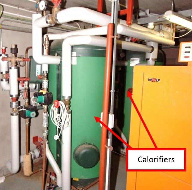
The general configuration of the domestic hot water system was typical of that used in hotels and other large buildings with multiple occupancy. The water was heated indirectly by a bank of boilers and stored in two, large insulated calorifiers, from which it was circulated around the building. Nothing about the configuration of the system had changed, with the exception of the addition and modification of the water softening system.
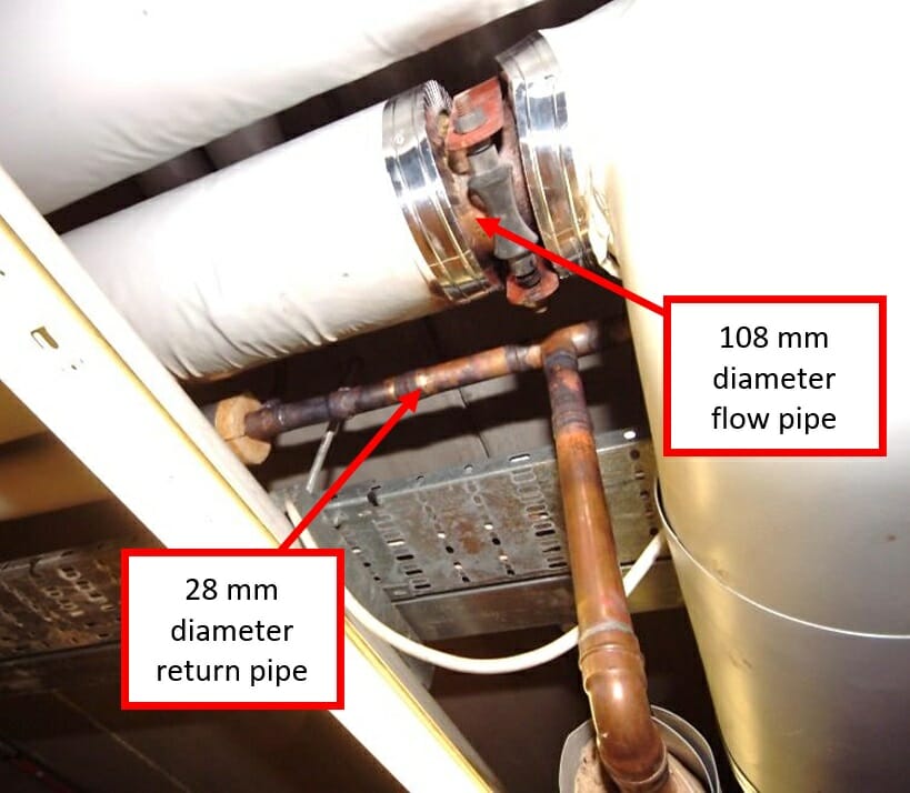
Each of the calorifiers was fitted with an electric-motor-driven circulation pump that was configured to produce a maximum water flow rate of 2 litres per second. Two 54 mm diameter flow pipes connected the cylinders to a single 108 mm diameter copper hot water distribution pipe. The corresponding ‘return’ pipe comprised a 28 mm diameter copper pipe, something that immediately gave me cause for concern.
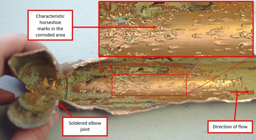
I was given a selection of the failed pipework that had been removed and replaced by the in-house maintenance team over the course of the preceding two years. It was noticeable that most of the pin-holes from which the water escaped had occurred immediately downstream of soldered elbow, or “T” connections.
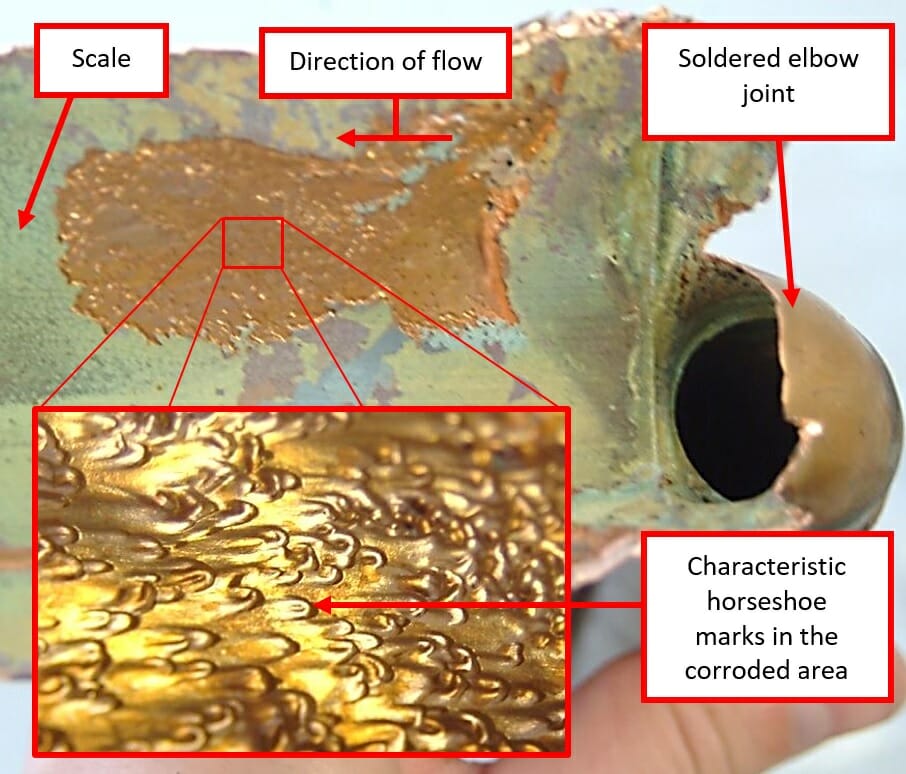
I sectioned the pipes in the laboratory to enable the internal surfaces to be examined. There was evidence of corrosion surrounding the areas in which each of the pin-holes had formed. The corroded surfaces were shiny and pitted with “horse-shoe” shaped marks surrounding the pits. The wall thickness of the tubes was also reduced significantly.
There was a thin layer of scale present on the non-corroded internal surfaces of the sections of pipework that had formed part of the original installation. However, there was no scale on one pipe that had been installed after the water softening system was introduced, which had then subsequently failed.
The patterns of corrosion damage were very distinctive and typical of patterns that occur as a result of a process known as erosion-corrosion.
Erosion-corrosion is a type of corrosion that is normally caused by a combination of high water velocities, turbulent flows and corrosive water. The high velocity turbulent flow strips away any protective scales and oxides from the inner surface of the pipework, which exposes the copper and allows it to be eroded and corroded by the water. The products of these processes are then swept away, exposing the underlying copper to further erosion and corrosion.
In general, British Standard design requirements require water velocities to be kept below 3 metres/second. However, in order to avoid erosion-corrosion related issues, water velocities in ring main hot water systems should be kept below 1.5 metres/second; although some published research suggests that problems are unlikely to occur at flow velocities below 2.5 metres/second. Notwithstanding this, there is also a requirement to maintain water velocities above 0.5 metres/second, in order to avoid other unrelated problems.
Copper pipes are available in a range of standard sizes based on the external diameter of the pipe. It has been standard practice in the plumbing industry for many years, when sizing pipework in ring main hot water circuits, to select a return pipe size that is “two sizes” smaller than the flow pipe, in order to achieve acceptable flow rates in both pipes.
In this instance, the flow of water through the system was maintained by two electric-motor-driven circulating pumps which acted in parallel and were capable of producing a combined maximum flow rate of 4 litres/second in the 108 mm diameter flow pipe. This would result in a flow velocity of just over 0.4 metres/second in the main flow pipe, which though just below the minimum recommended flow rate, was probably acceptable.
Nevertheless, at times of low demand (e.g. during the night) most of, or possibly all of, the water flowing through the flow pipe would have been returned to the calorifiers via the single 28 mm diameter return pipe, on which the pin-holes were forming. The reduction in diameter from 108 mm to 28 mm would have caused an acceleration of the flow by a factor of approximately 16, producing flow velocities in the region of 6.4 metres/second in the return pipe, which is well in excess of the threshold above which erosion-corrosion is likely to occur.
For a system with a flow pipe diameter of 108 mm, the appropriate return pipe diameter should have been 66.7 mm (i.e. two sizes smaller than the flow pipe); a 28 mm diameter pipe is “six sizes” smaller than the flow pipe. This was clearly not in accordance with industry practice, and was always likely to have caused problems. Therefore, it was clear to me that the issues had almost certainly occurred due to the excessive flow speeds caused by the erroneous sizing of the pipework. Nevertheless, the reasons for the problems only manifesting after the installation of the water softening system still required an explanation.
Both the original tests results and the available witness information indicated that the water from the borehole was scale-forming. Indeed it was the formation of scale within the pipework that had prompted the installation of the water softening system. Ironically, the formation of the scale appears to have been sufficient to protect the pipework from the potential adverse effects of the unduly high water velocity in the return pipework. The non-corrosive nature of scale-forming water would also have helped. However, following the introduction of the water softening system, the water became slightly corrosive, and this would have resulted in the removal of the protective layer of scale from the pipework, particularly in areas with high-velocity turbulent flow, leaving them vulnerable to damage by erosion-corrosion.
Whilst it seemed to both the operators of the hotel and their consultant that the softening of the water was the key factor that initiated the failure, the fact that the properties of the softened water were well within prescribed limits and the evidence that the leaks were only occurring in areas with excessive flow velocities indicated that this position was not valid.
In this case, considerable time and money were effectively wasted on pursuing what transpired to be the wrong party. An incomplete investigation was carried out by a party that not only had a vested interest in the outcome, but also made an erroneous interpretation of the evidence. This case was somewhat unusual, because the maintenance manager was very proactive in documenting and preserving the physical evidence; however, this is often not the case. It can be both useful and cost effective to instruct Hawkins at the earliest opportunity, so that a sound and impartial technical assessment of the issues can be made, and the appropriate actions can be taken.
ABOUT THE AUTHOR
John Holland is a Principal Associate and Chartered Mechanical Engineer based in our Glasgow Office. Since joining Hawkins, John has amassed considerable experience in the investigation of issues affecting both commercial and domestic plumbing systems.
John specialises in the investigation of fires, explosions, escapes of fluid, engineering failures, personal injuries – particularly those involving plant and machinery, building damage resulting from water ingress, and road traffic accidents.