20 7481 4897")


 Italiano
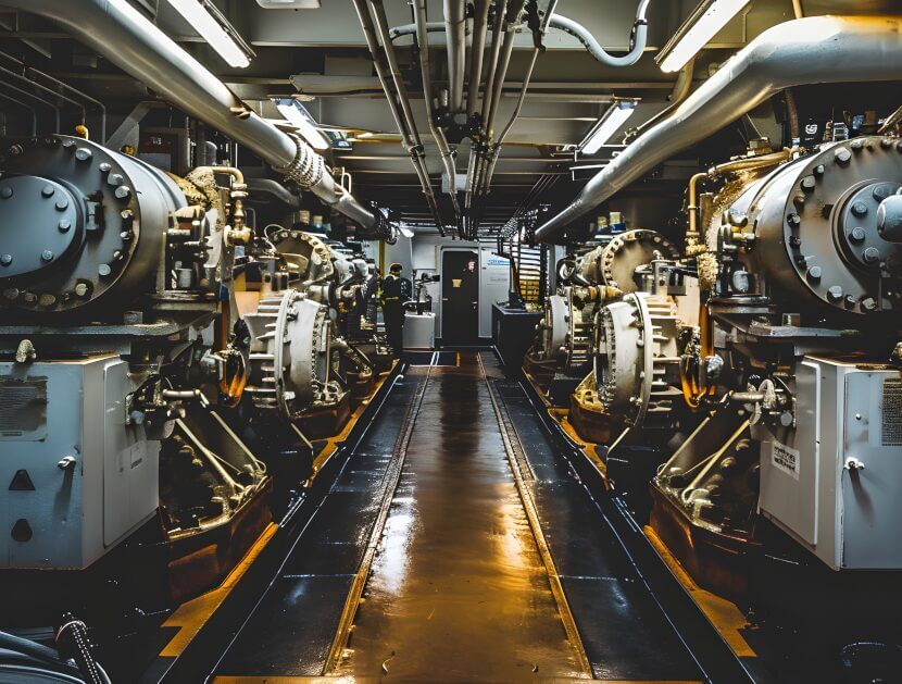

The Importance of Fuel Systems in Marine Operations
When combining diesel combustion engines with aeroderivative gas turbines in power generation assets and mechanical drive systems, the fuel specification and adherence to the specification are critical. Compliance ensures the optimal operation, and longevity of the asset and minimises down time.
In marine installations, large vessels can have a mix of propulsion drive systems. Typically, these consist solely of large diesel units, however, in some large vessels, the addition of gas turbines can be found – for that extra bit of thrust/speed.
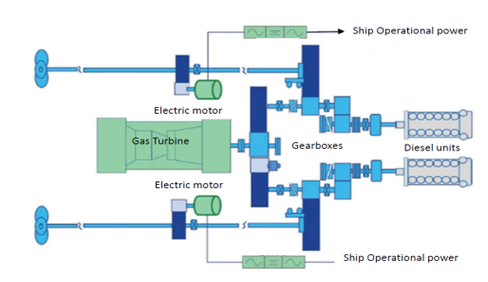
Both can be susceptible to damage and loss of power if issues exist within the fuel supply system, problems can be caused by using the wrong fuel, or if contaminants are present in the fuel system. If contamination occurs, this can lead to a sudden loss of power which can affect the safety of the vessel. Contamination can compromise the integrity of not only the engine, but also the fuel system, which will require draining and cleaning; both of which will be costly and time consuming to execute. A typical propulsion system schematic is shown in Figure 1. This shows two diesel units and one gas turbine in a two-propeller propulsion system.
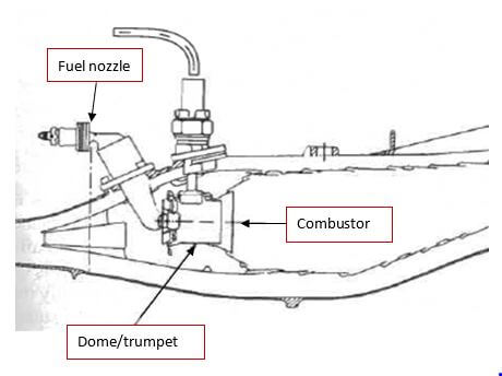
If fuel issues arise, both power unit types can be affected. In the example below, I look at how fuel contamination can lead to a buildup of deposits in the fuel system, especially in the final fuel delivery section, which in a gas turbine is the fuel nozzles. The fuel nozzles are complex components that premixes fuel with compressed air and inject the fuel mixture into the combustion can. Combustors see the hottest temperatures.
A schematic diagram of a typical fuel nozzle in a single annular combustor (SAC) is shown in Figure 2. The fuel nozzle is the final link prior to the fuel being atomised into the compressed air flow and ignited.
Issues in the fuel system can be detected by the gas turbine monitoring systems which include temperature and pressure sensors. In SAC gas turbines, there are around 30 fuel nozzles. If issues are developing, the temperature spread around the combustor is likely to change and exceed the permitted temperature spread which is typically limited to approximately 100 to 150°C across eight thermocouples dispersed around the turbine. The fuel pressures in the delivery pipework will also increase as blockages develop. These are both indicators of problems in the fuel supply system, and monitoring of the system’s sensors is of critical importance.
In the case study that follows, excessive temperature spreads and reduced power output were detected over a 72-hour period, indicating an issue with the combustion that required further investigation. This shows how rapid the degradation can be once coking occurs.
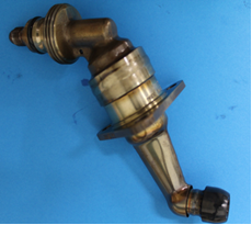
Once an issue has been identified, there are limited options for a vessel at sea. The first is to inspect the fuel nozzles to see if there are any visible signs of distress. If deposits are found as in the example below, then all the fuel nozzles will likely need to be replaced. On a gas turbine, each fuel nozzle can cost in excess of 5,000 USD, and a vessel will not carry a spare set on board.
To determine the source of deposits, a laboratory examination of the affected nozzles will be required.
A typical suite of tests includes:
- Visual examination;
- Sampling deposits;
- Optical microscope examination;
- Scanning Electron Microscope (SEM) and Energy Dispersive Xray Spectroscopy (EDS).
Case Study
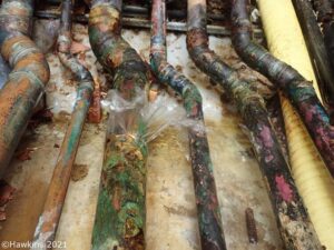
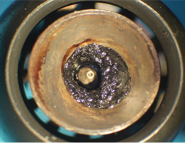
Visual examination of the nozzles from the gas turbine that had exhibited excessive T-48 temperature spreads (Figure 3), revealed remnants of liquid fuel, with both the primary and the secondary fuel line blocked by deposits. The primary flow line had been cleared prior to receipt into the laboratory but was reported to be blocked on removal from the gas turbine.
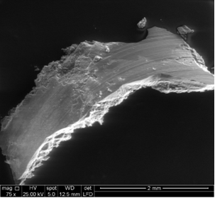
Within the residual fuel, solid deposits were found that were collected and examined. The solid deposits revealed a layered structure (Figure 4) consistent with deposits forming over several operating cycles (stops). This appearance is consistent with coking of the fuel during shut down and thermal soak back. Soak back is the cooling off period after shutdown and can be challenging as it can lead to very high temperatures in the engine damaging equipment back equipment¹. The appearance would also indicate that a purge cycle was not undertaken to remove residual fuel from the fuel line in the area.
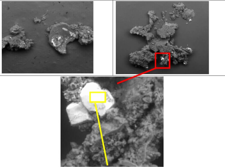
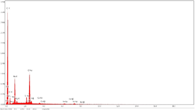
The samples collected were analysed using an EDS analyser attached to an SEM. This revealed the deposits to be predominately carbon, however significant traces of sodium (Na) and chlorine (Cl) were detected in areas exhibiting a cubic crystal form (Figure 5). The cubic crystals were observed in all samples examined.
The coking found in the fuel nozzles would indicate that issues were present in the purge sequence of the fuel lines on shut down. In most industrial gas turbine applications, on shut down, the fuel manifold is purged with compressed air to clear the line of residual fuel to minimise the possibility of coking. This did not appear to have occurred. The presence of cubic crystals of sodium chloride indicated contamination of the fuel by ingress of sodium chloride rich solute, such as seawater into the fuel system at some stage.
Besides the issues generated by the coking on the fuel combustion, the gas turbine had been exposed to elevated levels of sodium, which had passed through the high-pressure turbine section. At the temperatures in the hot section of the turbine (high-pressure turbine) this can lead to Type 2 hot corrosion of the turbine blades (which are more expensive than the fuel nozzles). This can lead to a catastrophic failure of the unit if not rectified.
Normally, sodium levels in fuels are specified/restricted to levels down to parts per billion to avoid this degradation mechanism. On the completion of the analysis, it was clear that further investigation was required, into the operating procedures and fuel monitoring during the operation of the vessel.
About the Author
Stephen is a forensic metallurgist with extensive global experience providing independent materials and corrosion advice to multi-national companies within the built environment and engineering industries.
He has over 25 years of experience undertaking failure and root cause analysis for clients in the power, process, and pipeline sectors and has acted as an expert witness across the globe.
¹Predicting engine soak-back with SALAMANDER | Clean (clean-aviation.eu)