
 Italiano



The Museum of the Future is often described as one of the most beautiful buildings in the world. This reputation is due in part to its unique façade, where the glazing forms quotes from the poetry of His Highness Sheikh Mohammed, the Ruler of Dubai.
The building’s structure is in the form of a diagrid with horizontal members spaced vertically every 4.5 metres.The diagrid supports both the internal floors and the external façade.
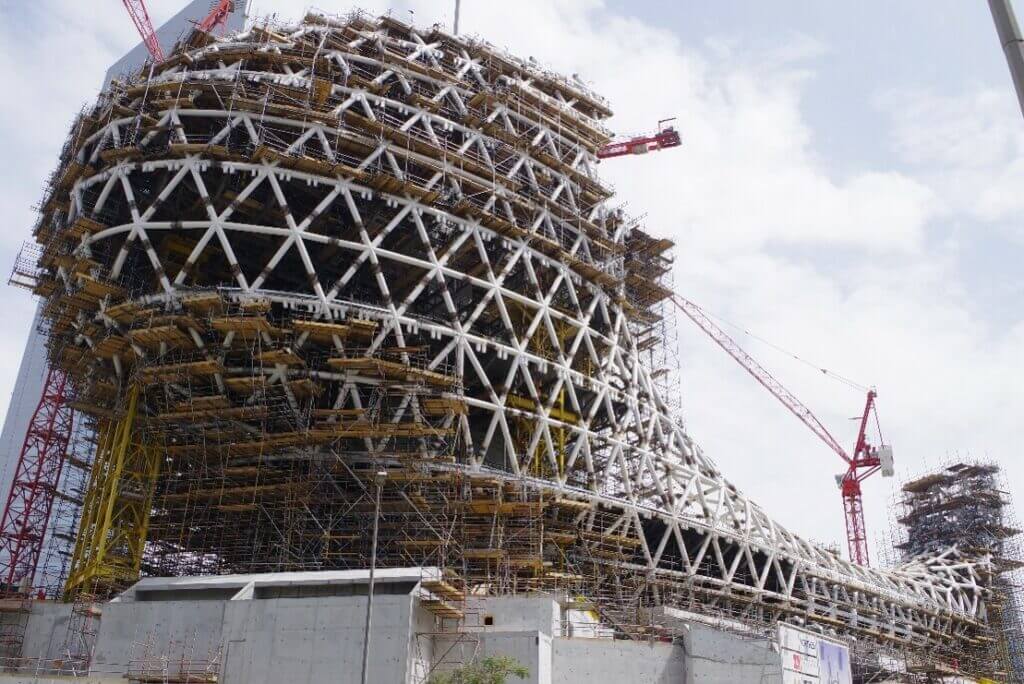
The façade comprises approximately 1,000 panels made from glass fibre reinforced polymer (GFRP) overlaid with stainless steel sheets. Due to the calligraphy writing forming the glazing, each panel is unique.
As might be expected on such a technically-unique project, there were a number of obstacles to overcome, particularly in the design of the project-defining façade. Indeed, the final cost of the façade was roughly double the tender price submitted by the façade sub-contractor, with each panel ultimately costing around AED 250,000.
The main contractor and the façade sub-contractor were unable to agree on how these cost increases had arisen or which party should bear financial responsibility. This resulted in proceedings before the Dubai International Financial Centre (DIFC) Court, where I acted as an independent expert to help the Court determine these complex issues.
So, how could the tender price differ so dramatically from the final cost? Did the façade sub-contractor underprice the works, or did something more fundamental cause the cost to increase?
Background
The façade was tendered on the basis of a performance specification which stated:
“Drawings and information in this Specification are intended to show the general form and arrangement of the cladding, and basic cladding systems, including modules and envelopes of space allowed for cladding that must be adhered to. The contractor shall complete the engineering design of the cladding to comply with this Specification and shall be responsible for the design supply and installation of the cladding. The visual aspects of this design must be maintained.”
With regard to design responsibility the specification stated:
“This is a performance specification, accompanied by drawings showing the design intent. The contractor shall be responsible for the development of any information beyond IFC to reflect any specific design or technical aspects required by the specialist façade sub-contractor. The façade drawings issued as part of the tender package reflect the detailed design, and the specification outlines the required technical performance of the building envelope.”
The GFRP system was described as having a “stainless steel cladding or skin bonded…”
Horizontal and vertical joints were stated to be “as indicated on the contract drawings.”
The tender drawings for the façade stated that panel sizes were to be:
“2.5m x 4.5m or 9m x 3m, vertical span 4.5m or 9m typ (to preferred contractor module)…”
The panelisation process was described as:
- Preliminary subdivision of façade surface along horizontal diagrid members.
- Secondary transversal subdivision to achieve panel sizeswithin themaximum allowable limits by main UAE suppliers of GFRP and close to single curvature configuration.
- Manipulation of the panel geometry to minimise the deviation from single curvature within an acceptable tolerance for the manufacture of thestainless steelcladding is undertaken. Panels are single curved with limited areas of minimal double curvature.
Within its tender response the façade sub-contractor stated:
“The Panels of Main façade are proposed to be 9 Mtr. x 2.20 Mtr. in size with double curvature to achieve the required outer surface.”
As part of its tender return, the façade sub-contractor produced a mock-up to show that production of its preferred panel size was feasible. The mock-up indicated that the stainless steel sheets were to be mechanically fixed to the GFRP panels using rivets, as the adhesive alone could not be relied upon to secure sheets to the GFRP panels.
A letter of intent (LOI) was issued to the façade sub-contractor within which is stated:
“All qualifications, exclusions, clarifications, etc. stated within the subcontractors quotation shall be deemed withdrawn and shall not form part of this Letter of Intent…”
Attached to the LOI was a list of issued for-construction drawings and documents. The content of these was identical to the tender documents; they had not been updated to reflect the façade sub-contractors tender proposal.
The façade sub-contractors contract included that “The Sub-contractor is to allow for all design changes of a minor nature.”
Post contract, the client and consultant team requested that a number of alternative panel module options be developed. It was submitted that this went beyond simply assisting with the finalisation of the design, and instead removed the façade sub-contractor’s contractual right to develop its own preferred module size, as stated in its tender proposal.
The “approved” panel module size resulted in panels significantly larger than the 9×2.2m units on which the façade sub-contractor had based its price, with the sub-contractor alleging that over 70% of the panels exceeded this size. This not only required a greater volume of foam to create the moulds for the GFRP panels, but also necessitated changes to the fabrication and production processes.
Following the production of visual mock ups, the proposed use of rivets to mechanically fix the stainless-steel sheets was rejected. Instead, welded studs were introduced. These studs had to be welded to the back of the stainless-steel sheets in a manner that avoided any burn marks on the visible face., This added a further production step to ensure precise alignment with corresponding holes in the GFRP panels.
In addition, vertical hairline joints between the stainless-steel sheets bonded to the GFRP panels were rejected, with full length sheets across width of the panels requested to mitigate the need for vertical joints between the stainless-steel sheets.
The increased panel size and curvature also created difficulties in bending the stainless-steel sheets to match the panels. To overcome this, a hexagon scoring pattern was introduced which involved laser cutting slots in the stainless-steel sheets to improve its ability to conform to the panel curvature. Moreover, the horizontal joints between sheets were requested to be cut with a ‘zig zag’ pattern to give the impression of a single continuous stainless-steel sheet on each GFRP panel.

Parties’ Positions
The façade sub-contractor submitted that it was unable to verify the additional cost arising from these changes, relative to its tender proposal, until a number of panels had actually been produced. Once this had occurred, the façade sub-contractor suggested the cost would now be double the amount originally tendered.
Despite the changes introduced, the sub-contractor’s claim for additional costs was rejected. Moreover, the client and its design team rejected the visual mock ups without reference to the specification or to any non-conformance with the Contract documents. They further asserted that the introduction of the hexagon scoring pattern was required to address the façade sub-contractor’s alleged inability to resolve bonding issues between the stainless steel sheets and the GFRP panels, and was a means of achieving the design intent of stainless steel bonded to the GFRP over a doubly curved surface, despite the original intent being a single curved façade.
Court’s Findings
In its judgment, the Court agreed that the changes in the panel size were not “minor”, expressly accepting the expert evidence of Mr Smith regarding the panel sizes having been increased beyond 9m x 2m. The Court was satisfied that changes to the design, increased panel size and the introduction of the hexagon pattern were for aesthetic reasons, and “not based on engineering necessity”.
Whilst it was intended for the contractor to complete the technical design of the façade, the performance specification and design intent were found to lack sufficient constraints to maintain the architect’s vision without the need for design changes during the contract works.
In accordance with the contractual documentation, the panel sizing was defined but was for the façade sub-contractor to develop in line with its preferred approach. However, the Court found that the façade sub-contractor was not permitted to develop its preferred module size, and therefore it could not be held responsible for the increase in costs.
The Court also determined that the specification was not sufficiently detailed to prohibit the use of visible fixings. If the intention had been to require ‘secret’ or ‘invisible’ fixings, such terminology should have been expressly included. Instead, the specification merely stated the stainless-steel sheets were to be bonded to the GFRP panels.
Similarly, neither the specification nor the drawings were sufficiently detailed to prescribe the required joint location or the joint pattern.
These findings, including the Court’s acceptance of Mr Smith’s expert evidence on the nature and impact of the design changes, highlight the importance of clear, unambiguous, and robust specifications and contract documents. Such clarity minimises gaps in information, reduces the risk of unexpected cost increases, and helps prevent disputes.
Postscript
Please note that the contents of this article are based on publicly available information and drawn directly from the judgment in the DIFC Court proceedings. The outcomes of these proceedings also relied on the specific contractual framework in place between the parties. Accordingly, any dispute arising in similar circumstances will ultimately depend on its own specific facts. On that basis, this article is provided for information only and does not constitute technical or legal advice.
About The Author
Austen Smith is a Hawkins’ forensic expert based in our Dubai office. He appeared for the façade sub-contractor in the above case. He opines on building failures due to defective design and workmanship, fire safety defects, scope of work, design approvals, and variation disputes amongst others. Austen is registered with the Architect’s Registration Board, is a member of the Royal Institute of British Architects, the Chartered Institute of Building, the Chartered Institute of Arbitrators, the Society of Construction Law and the Academy of Experts, and is on the roster of arbitrators with the Saudi Centre for Commercial Arbitration.