20 7481 4897")


 Italiano
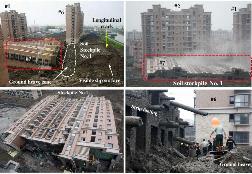
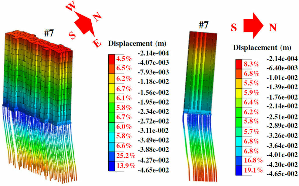
Top Right: right after toppling of Building 7
Bottom Left: view of Building 7 after failure
Bottom Right: view of the foundation and ground below
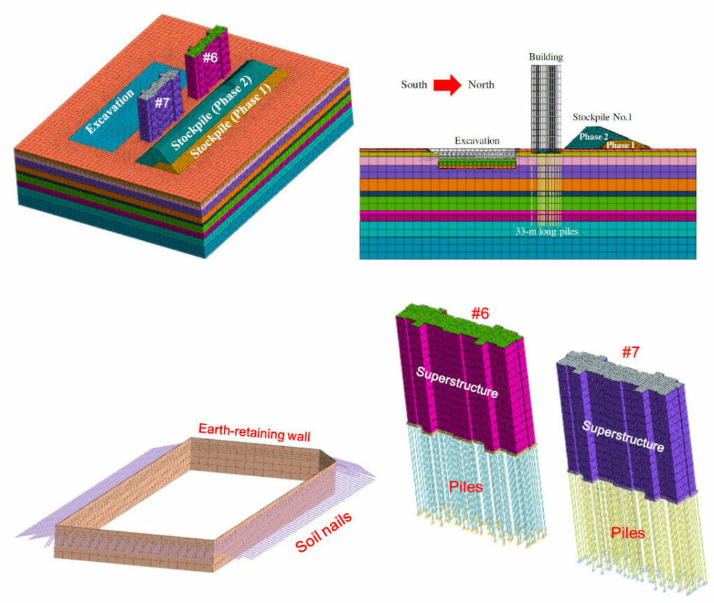
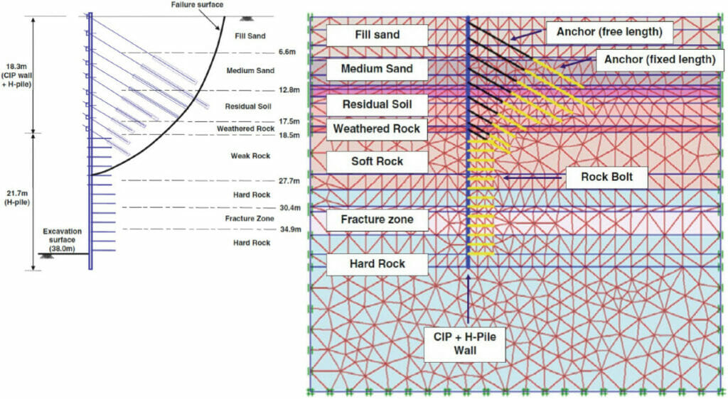
Top Right: Side View
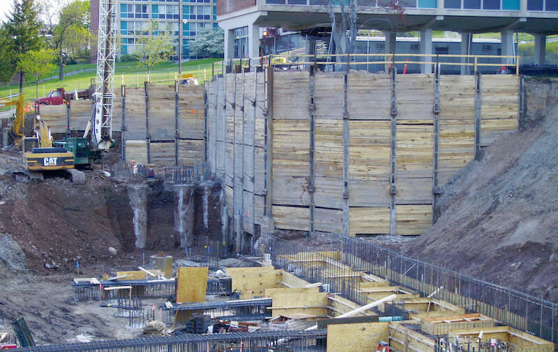
Bottom Left: Temporary Earth Retaining Structures for the excavation
Bottom Right: Superstructures and pile foundations of the buildings
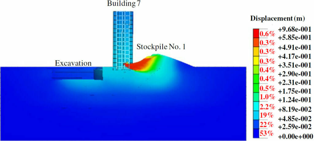
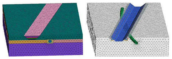
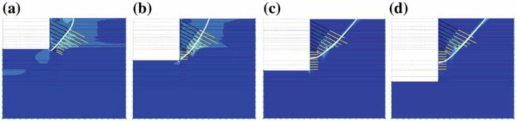
Left: side view of simulated total ground displacement
Right: top view of simulated vertical ground displacements (positive, heave; negative, settlement)